This Maker Monday, Phil King shares some of the newer RP2350-based boards that have come to market since we last looked at similar devices back in issue 148 of Raspberry Pi Official Magazine. Just like before, these examples demonstrate the flexibility and versatility of our microcontrollers.
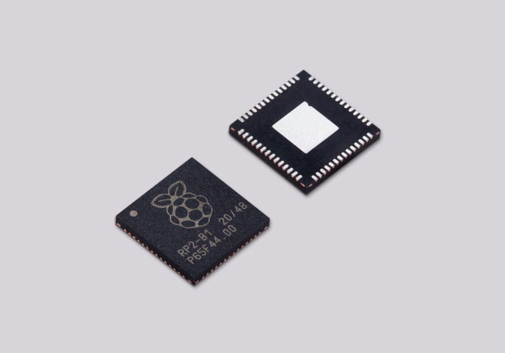
The RP2350 microcontroller is the brains of Raspberry Pi Pico 2, along with a host of third-party boards. RP2350 features dual Arm Cortex-M33 processors running at 150MHz, 520KB of on-chip SRAM, and twelve PIO state machines. So, compared with the RP2040 microcontroller from the original Raspberry Pi Pico, it offers a major performance boost for handling more complex computational tasks. It’s no wonder it’s been used in such a wide range of third-party boards and devices — you can check out the full selection in the Powered by Raspberry Pi product catalogue.
We’ll be taking a look at a few of the most interesting ones here, equipped with a variety of special features such as battery power inputs, extra GPIO pins and connectors, motor/servo controllers, Ethernet ports, IMUs, and even mini LCD touchscreens.
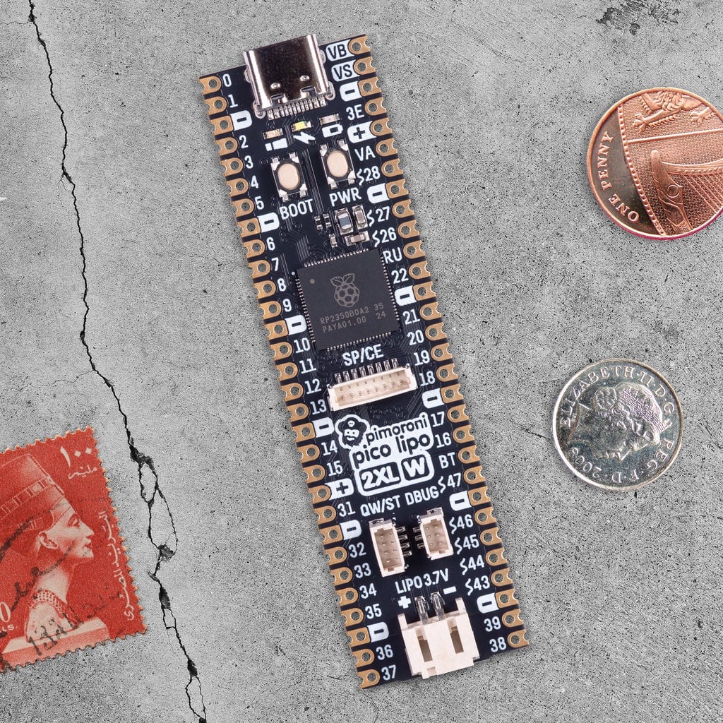
Pico LiPo 2 XL W
Pimoroni | £21 / $23
Did you know that there are actually two main versions of the RP2350 microcontroller chip? There’s the standard RP2350A used in Raspberry Pi Pico 2 and many third-party boards, and RP2350B, which adds 20 more pin connections — including 16 extra GPIO pins and five more ADC channels.
Pimoroni’s Pico LiPo 2 XL W makes full use of RP2350B with an elongated board that breaks out those 20 extra pins. Helpfully, the rest of the pinout is the same as the standard Raspberry Pi Pico one, and all the (unpopulated) pins are labelled on the top of the board, so it’s easy to find the ones you need. Memory and storage have also been super-sized, with 8MB of RAM and 16MB of flash.
A USB-C connector is used for power and programming. You can also power the board from a LiPo or Li-ion battery (not supplied) via a two-pin JST connector; there’s on-board battery management and charging circuitry.
Other features include connectors for Qwiic and STEMMA QT, debug, and SP/CE (SPI/serial), along with boot/user and power buttons. A Raspberry Pi Radio Module 2 provides Wi-Fi and Bluetooth connectivity.
Verdict
Extra GPIOs, battery input/charging, and much more.
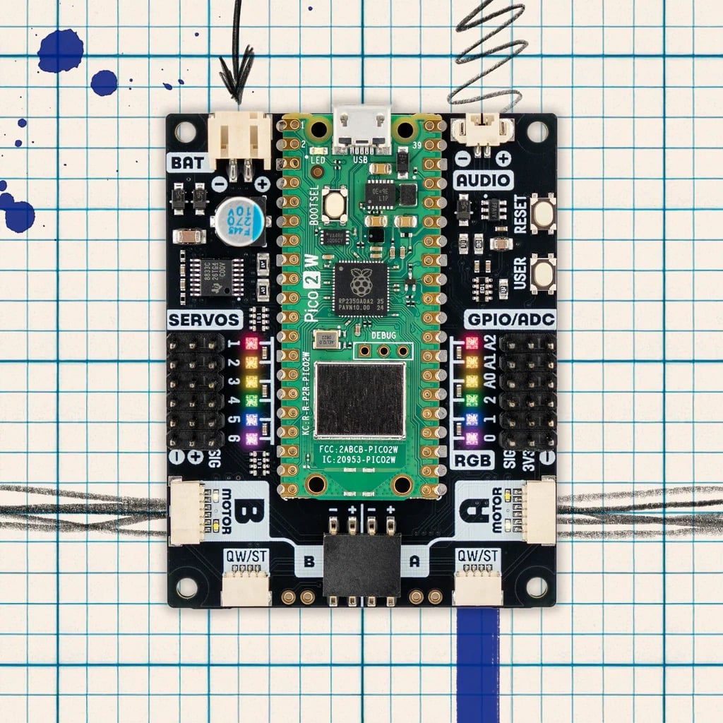
Inventor 2350 W
Pimoroni | £35 / $38
With myriad connections and extra features, this versatile board makes it easier for beginners to get started with coding and electronics. It’s powered by a standard Raspberry Pi Pico 2 W (with built-in wireless connectivity) soldered to the top of the board, surrounded by ports, pins, NeoPixels, and buttons — an identical layout to that of the excellent Inventor 2040 W it supersedes.
For robotics, there are headers for up to six servos, along with an on-board motor driver connected to two JST-SH ports. The latter are for connecting encoder-equipped motors, but you can still wire standard ones up to a four-pin connector.
There are also six GPIO headers (including three analogue inputs), two Qwiic/STEMMA QT ports (for sensors), an I2C/Breakout Garden unpopulated header, a JST-PH input for optional battery power, a two-pin connector for 1A at 1.5W audio output, plus handy ‘User’ and ‘Reset’ buttons. Phew!
Software-wise, the Inventor 2350 W is easy to use, thanks to comprehensive libraries and code examples for MicroPython and C/C++.
Verdict
A feature-packed board, ideal for electronics and robotics.
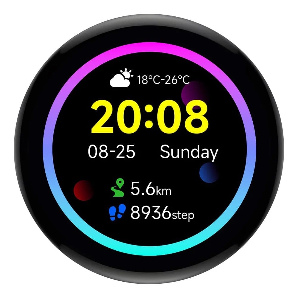
RP2350 1.43-inch AMOLED Round Display Dev Board
Waveshare / The Pi Hut | £23 / $31
Most Pico-style boards lack any form of display, though you can buy add-ons to enable video output. Waveshare, however, produces a range of RP2350-based devices with built-in displays in various shapes and sizes.
This particular model is circular and comes with an optional metal case with cut-outs for the boot and reset buttons, USB-C port, microSD card slot (for extra storage), I2C and UART four-pin headers, and GPIO breakouts on the rear.
With a 466 × 466 pixel resolution, the colour AMOLED screen looks vibrant and has capacitive touch. Combined with the built-in six-axis IMU and an RTC with a battery header, it could easily be used for a wearable or pocket project like a fitness tracker.
While the MicroPython firmware is limited to a handful of code examples, the C/C++ firmware is far more comprehensive, including the use of LVGL (Light and Versatile Graphics Library) to render text, images, and an example GUI complete with animated graphs and a tiny pop-up keyboard.
Verdict
A very slick RP2350-based touch display with a built-in IMU.
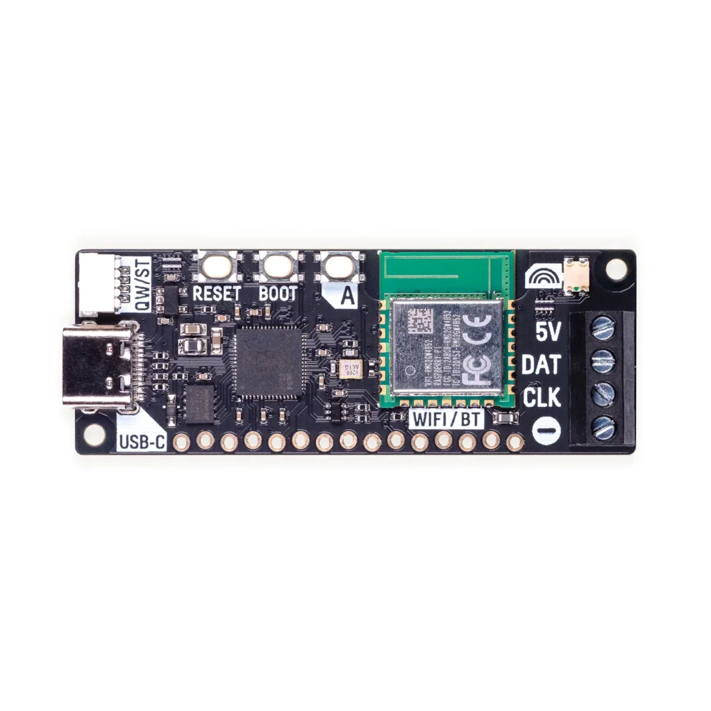
Plasma 2350 W
Pimoroni | £17 / $18
We reviewed the original Plasma 2350 back in issue 148, and now there’s a version with built-in wireless connectivity, opening up extra possibilities for controlling a connected strip of WS2812/NeoPixel or APA102/DotStar RGB LEDs. The optional starter kit includes a 10m string of 66 frosted LED stars.
It’s dead easy to get started. Just connect your LED string’s three or four wires to the board’s screw terminals, then use its USB-C port to access the MicroPython firmware, library, and numerous code examples on a computer. Impressive effects include falling snowflakes, alternating/random blinks, sparkles, fire, pulsing, and a sweeping rainbow. More can be found in some community resources, including an impressive demo with 77 effects.
To give the board access to your wireless network, you’ll need to add your Wi-Fi details to a secrets.py file. You can then try out web-based examples, such as setting the colour of the LEDs via the CheerLights IoT system on social media, or running a lighting effect that responds to the weather from Open-Meteo.
Verdict
An easy and fun way to control a string of addressable LEDs.
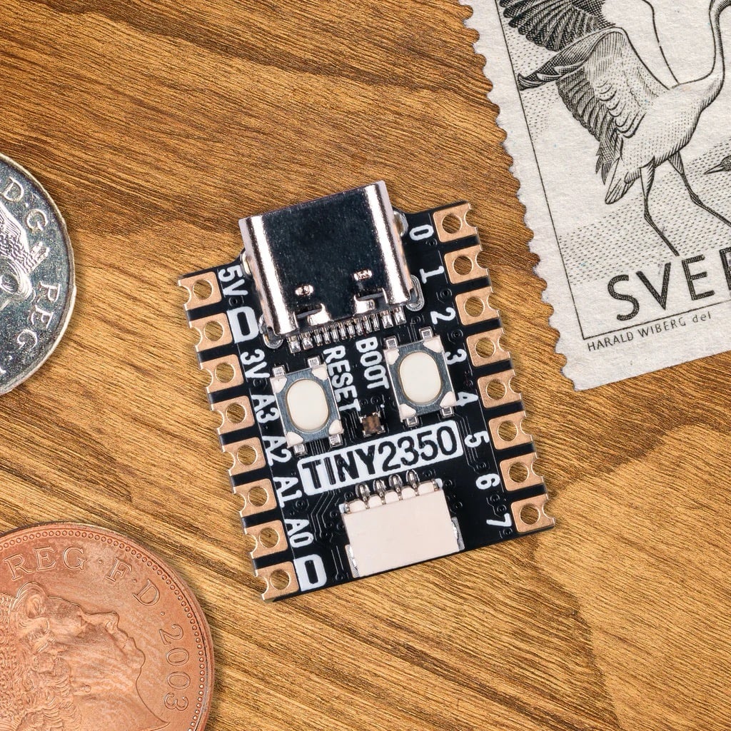
Tiny 2350
Pimoroni | £8 / $9
If you need a really small RP2350-based board for a project where space is very limited, the Tiny 2350 is ideal. Measuring a mere 22.9 × 18mm, it really is tiny — around the same size as a standard UK postage stamp.
Along with a boot select button, the board crams in a handy reset button, RGB LED, and 4MB of QSPI flash storage, though there’s no wireless connectivity. A USB-C port is used to power the board, and to connect it to a computer for firmware installation and coding in MicroPython, CircuitPython, or C/C++.
The Tiny 2350 is available with or without pre-soldered pin headers. One obvious downside is that the number of pins is reduced compared to a standard Raspberry Pi Pico 2. There are 16 in total, including 12 GPIOs (plus another couple on the Qwiic/STEMMA QT port). They include four 12-bit ADC channels, though, and encompass two channels each of the I2C, SPI, and UART protocols.
Verdict
A teeny-tiny RP2350 board that’s ideal for smaller projects.
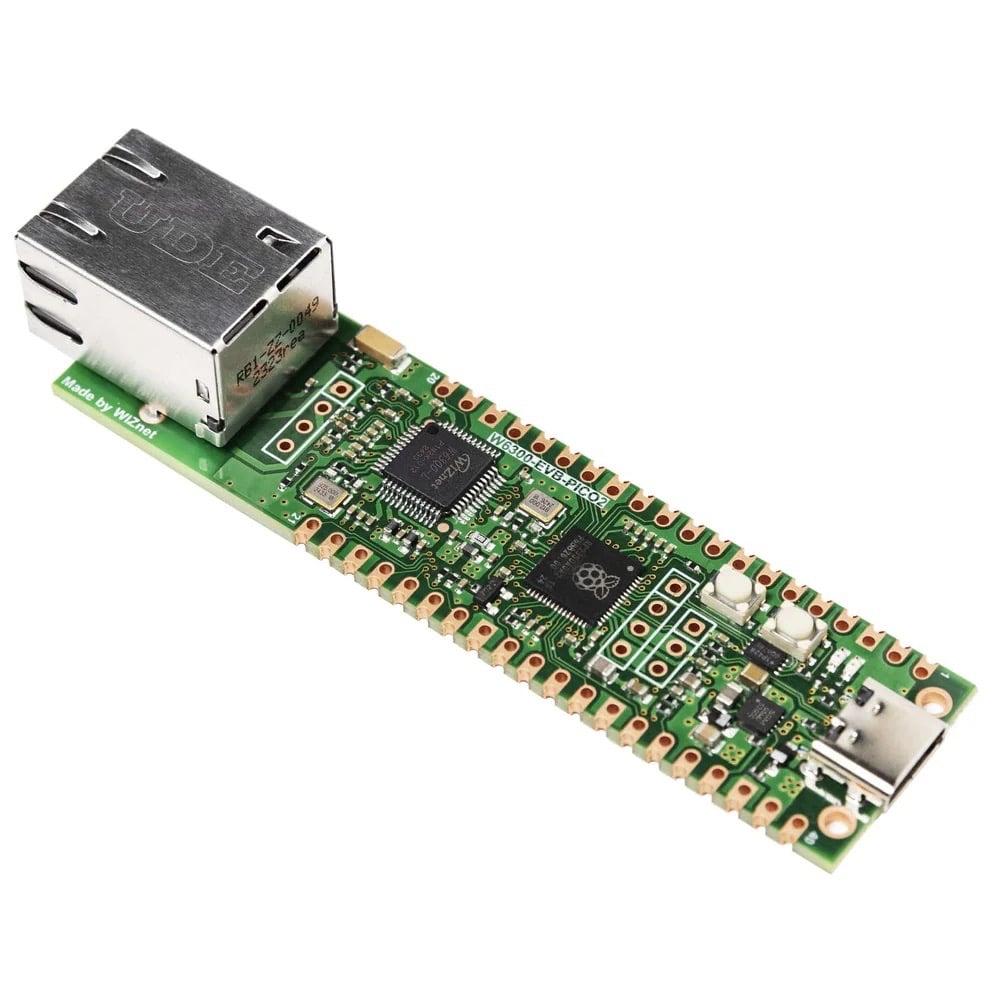
W6300-EVB-Pico2
WIZnet / The Pi Hut | £11 / $15
While many RP2350-based boards boast built-in wireless connectivity, sometimes you may need a wired Ethernet connection for improved reliability, security, and speed. Possible projects include a low-power HTTP web server, network monitoring, IoT data logging, and industrial devices.
WIZnet produces an Ethernet HAT to use with standard Raspberry Pi Pico boards. Alternatively, you can use one of the firm’s range of Ethernet-equipped RP2040 and RP2350 devices. This RP2350 one is based around WIZnet’s own W6300 chip: a 10/100 Ethernet controller with a hardwired TCP/IP stack that supports both IPv4 and IPv6 — as do the W6100 models, while the W5500-based boards are limited to IPv4.
All of them feature an identical pinout to Raspberry Pi Pico and Pico 2, with 40 pins and 26 multi-purpose GPIOs, so it’s all very familiar. The documentation includes C/C++ firmware/code examples for Ethernet, FreeRTOS, AWS, Azure, and chip performance. There’s no MicroPython firmware available for the RP2350 models yet (unlike the RP2040 ones); hopefully that will come soon.
Verdict
Perfect for projects requiring a wired network connection.
The post Maker Monday: Some of the best RP2350-based boards appeared first on Raspberry Pi.
from News - Raspberry Pi https://ift.tt/y0XFT94