The latest issue of Raspberry Pi Official Magazine dives into marine technology, discovering some Raspberry Pi–powered sea-based projects. We particularly liked this guide on how to build a tiny open-source underwater vehicle with Raspberry Pi Pico.
About a decade ago, we were inspired by a workshop at Liverpool Makefest where an organisation called the Dark Water Foundation made all manner of water monitoring devices.
Dark Water Foundation got attendees to make miniature palm-sized underwater rovers using Lego, 35mm film canisters, and some small brushed DC motors. “DC motors?” I hear you cry. Well yes, the revelation on seeing this workshop was that small 3–6V DC motors run really well in fresh water without any attempts to waterproof them. The caveat being you are probably shortening their life somewhat, and you need to do a little work to dry them out after each mission.
Many of the original links to this workshop are now missing; so, with absolute respect for the original project, we decided to make a more modern attempt influenced by that original design. There still is an Instructables page with some images and component lists, but sadly the links to components from the page aren’t currently working, so we’ve made some educated guesses and experimented to come up with a working solution.
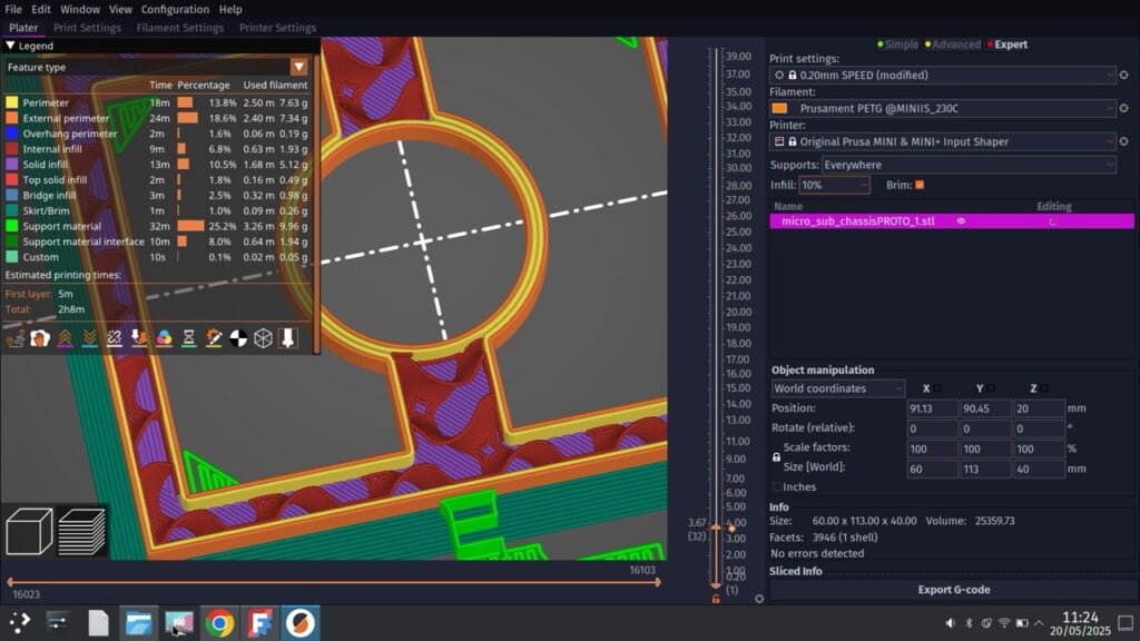
The original design was around a 60–75mm cube for the frame made from Lego. We set out to 3D-print a similar-sized frame using the free and open-source FreeCAD package to realise our ideas. The original design used 30mm brushed DC motors and we discovered that these at the time were rated to 5400rpm. We couldn’t find that exact specification, but found some close enough listed as 3–6V and 6500rpm. These are perfect because we intend to make a moderately more advanced controller for our design — we can use motor drivers to control our speed.
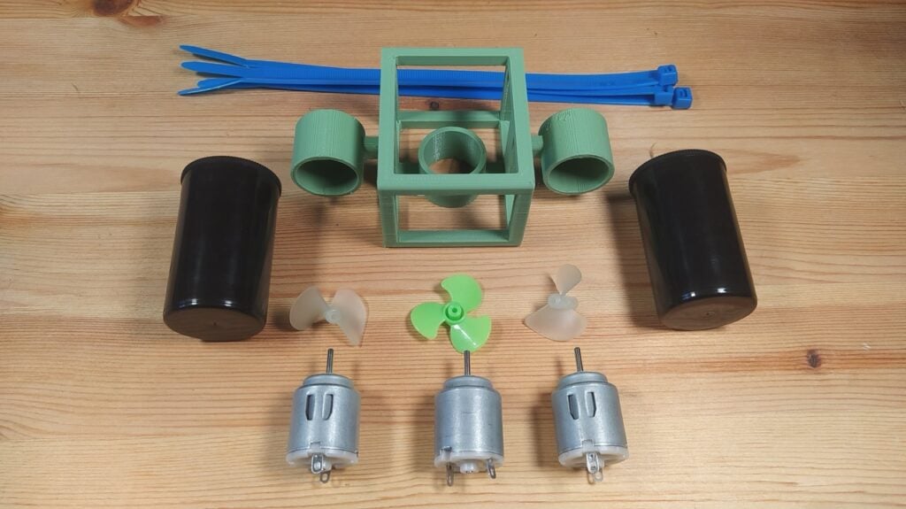
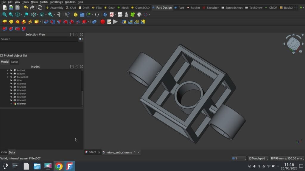
Once the motors arrived (Figure 1), we could then grab a set of callipers and take some motor measurements and begin our CAD work. In FreeCAD, we used the Part Design workbench to create the chassis, building up the frame by adding sketches to faces and extruding them (Figure 2). Our main chassis area is a cuboid frame with three thrusters: two set up for forward and turning (and potentially reverse if needed) on the sides of the frame, and one inside the frame, set in the vertical axis to control vertical position. The two horizontal thruster mounts are offset slightly from the centre in an attempt to distribute the weight a little.
Part of the design led us to consider what our buoyancy approach might be. There are two or possibly three options. We can either aim for absolute neutral buoyancy, where the vehicle neither descends or ascends in the water until a motor turns, positive buoyancy where the vehicle always wants to float and the Z-axis thruster pushes it down, or negative buoyancy where the vehicle always sinks until the Z-axis thruster supplies lift. Of course, the optimal is neutral buoyancy, but this is hard to achieve, particularly when you have tether wires which change the mass of the setup as it moves; also, for neutral buoyancy, we’d need to be able to switch the rotation of the Z-axis thruster.
Negative buoyancy is reasonably easy to achieve. We are going to add two 35mm film canisters (still widely available online) and we can simply fill these with water to make the vehicle sink. Neutral buoyancy has some advantages and disadvantages. An advantage is that if you completely fill the film canisters with water then they are equal and balanced — if they are part full, it can be difficult to not have the water move around and change the orientation of the vehicle. The disadvantage of negative buoyancy is that it uses a little more power as you’ll use the thruster a lot more. And if for some reason the power or motors fail, your vehicle will sink — perhaps not too much of an issue at this scale as you can pull it out by the wire tether.
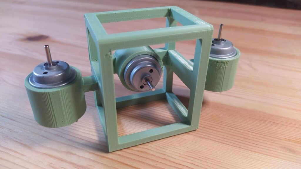
After printing a test frame in PETG filament, the assembly of the vehicle is pretty straightforward. With a reasonably well-calibrated 3D printer, the thruster mounts are tight enough for the motors to be a push fit (Figure 3). We used some 26mm two-blade nylon propellers for the horizontal thrusters and a larger three-blade 30mm propeller for the Z-axis, making sure to order ones with the correct 2mm holes to mount to our 30mm 3–6V brushed DC motors.
It’s important to try and find a balance of long wires that are thin and flexible to create the power lines for the motors. We found an old three-metre network patch cable that we pulled apart to get long lengths of suitable wire. If you wanted to spend rather than find something from your junk cable pile, you could probably find thinner and more flexible solutions. As the chassis sits quite nicely on a worktop, we inserted the motors into the chassis and then soldered the wires on, using the chassis as a helping hand.
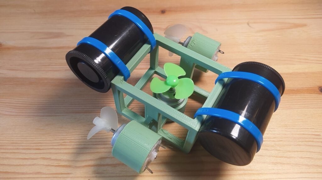
Adding the buoyancy tanks is as simple as two cable ties wrapped around the chassis and the 35mm film canisters (Figure 4). You can experiment with the position of the tanks slightly after they are fitted. If you place them more out in the front and the rear, if the vehicle is floating you might find your Z-axis thruster sits slightly out of the water. Raising the tanks above the vehicle means the Z-axis propeller is always covered in water.
Once you have your motors in place and wired and you have fitted the buoyancy canisters, it’s time to test. We ran our first tests by simply holding the motor wires across an 18650 battery momentarily to work out the polarity. With all that identified, we then couldn’t resist playing with it in a washing-up bowl full of water. This proves quite worthwhile as although you can’t really do too much, you can get a sense for if you want to have positive or negative buoyancy and play with adding different amounts of water to the floatation canisters.
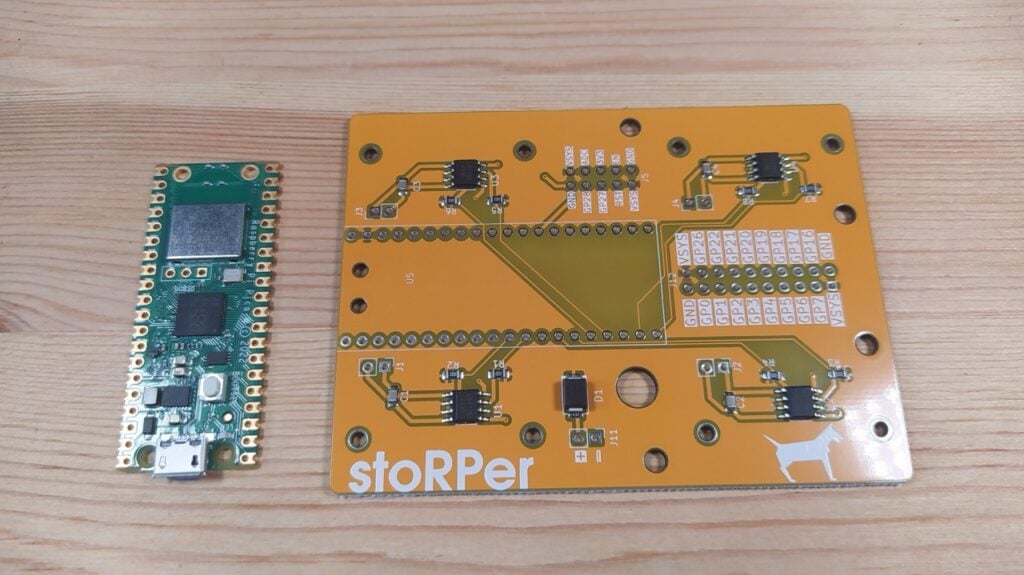
At this point, you could certainly make up a straightforward controller box with just some buttons or switches for each motor and some batteries. However, we went with the addition of a Raspberry Pi Pico as a controller, as this allowed us to drive the motors using pulse-width modulation (PWM), which allows us to control their speed and direction. To do this, we needed to use some motor drivers and we actually used a StoRPer board, which is a PCB we made as part of our Design an RP2040 board with KiCad book and articles that featured in HackSpace Magazine. The StoRPer board (Figure 5) is essentially a breakout board that connects some of Pico’s GPIO pins to four DRV8833 motor drivers. You could totally emulate this board on a breadboard using the StoRPer schematic and components; however, DRV8833 motor drivers are commonly sold as small modules on breakout boards and that would make for a simple option.
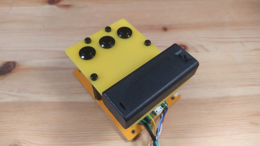
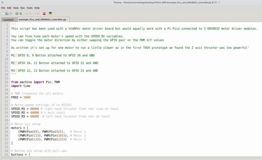
For our first controller system, we mounted three momentary press-to-make buttons in a panel (Figure 6) and connected them to Raspberry Pi Pico’s GPIO. In the MicroPython code (Figure 7), we have identified the GPIO pins for the buttons and defined them and set up a PWM system for each of the motors. Swapping the pair of pin number values for each motor can then reverse that motor and we can also change the speed values for each motor.
For our more serious testing, we moved to a second-hand inflatable hot tub. These can often be found second-hand, neglected and filthy, for very little money and make for an excellent large test environment for water-based projects. We gave ours a pretty good scrub and when we filled it, we gave it a dose of chlorine to kill off any bugs a couple of days before using it (to allow the chlorine to dissipate). As an aside, it’s great fun to place an action camera in a waterproof case in the tub/tank and capture some footage/images of your underwater test missions! Here is a link to an edited minute of underwater testing.
One thing we will change is that our wires are hard-wired to the controller and it would be beneficial, especially at the testing stage, to be able to quickly remove the wires so the controller alone can be taken back to the laptop inside (not near the hot tub) for code tweaks. We did a lot of drying of the vehicle and wires every time we needed to make a change. We powered our system a couple of different ways: either with an 18650 cell or with a USB power bank. With the 5V of the power bank, the motors spin quite quickly and the vehicle has too much thrust and is difficult to control, but this is easily rectified with changes to the speed values in the MicroPython script. We’re currently set up with a slight positive buoyancy with the Z-axis thruster set to turn a lot slower than the horizontal thrusters as it’s nice to be able to descend smoothly and gradually. We’ve also ended up drilling the small holes in the chassis to flood the chassis when submerged.
It’s great fun to tinker with and we have a few ideas for improvements. It would be great to make the wiring a little more flexible with some thinner and more flexible wires. We’d also like to add more functions to the controller. A switch to reverse the direction of the horizontal thrusters would be nice, as well as some latching switches that can set motors to be permanently running at a slow rate, perhaps even with potentiometers to vary the speeds. For example, we could set a slow speed for the Z-axis motor that, when activated, counters the positive buoyancy, allowing the TOUV to have a kind of ‘altitude hold’. It could be fun to add attachments like a hook or a magnet for fun ‘rescue the object’ games and challenges. We would of course love to get a camera on board, and sensors and more functionality, but we think that might be best on a larger DIY submersible project. Keep an eye out for that in the future. In the meantime, if you want to build a TOUV, the files are in this GitHub repository.
Raspberry Pi Official Magazine #157 out NOW!
You can grab the latest issue right now from Tesco, Sainsbury’s, Asda, WHSmith, and other newsagents, including the Raspberry Pi Store in Cambridge. It’s also available from our online store, which ships around the world. And you can get a digital version via our app on Android or iOS.

You can also subscribe to the print version of our magazine. Not only do we deliver worldwide, but people who sign up to the six- or twelve-month print subscription get a FREE Raspberry Pi Pico 2 W!
The post Build a tiny open-source underwater vehicle appeared first on Raspberry Pi.
from News - Raspberry Pi https://ift.tt/sdmDZBo


No comments:
Post a Comment