Tuesday, July 15, 2025

The Computers that Made the World — out now!

Chances are good that you’re reading this post on something quite small. Even if your computer is big by today’s standards, it’s nothing compared to the first digital computers. The latest book from Raspberry Pi Press, Tim Danton’s The Computers that Made the World, tells the story of the birth of the technological world we now live in, all through the origins of twelve influential computers built between 1939 and 1950.

This book transports you back to a time when computers were not mass produced, but lovingly built by hand with electromechanical relays or thermionic valves (aka vacuum tubes). These were large computers, far bigger than a desktop computer. Most would occupy (and warm!) a room. Despite their size, and despite the fact that some of them would help win a war, they had a minuscule fraction of the power of modern computers: back then, a computer with one kilobyte of memory and the ability to process one or two thousand instructions per second was on the cutting edge. The processor in your mobile phone probably processes billions of instructions per second, and has a lot more than one kilobyte of main memory.

A blue background with white, yellow, and navy abstract computer symbols frames the title in bold text. Text reads: The Computers That Made the World; Tim Danton.

From human computers to digital computers

In 1940, a computer was someone who ploughed through gruelling calculations each day. A decade later, a computer was a buzzing machine that filled a room. This book tells the story of how our world was reshaped by such computers — and the geniuses who brought them into being, from Alan Turing to John von Neumann.

You’ll discover how these pioneers shortened World War II, and learn hidden truths that governments didn’t want you to know. But this isn’t just a story about how these computers came to be, or the fascinating people behind them: it’s a story about how a new world order, built on technology, sprang into being.

Two facing pages from the book, The Computers that Made the World. On the left, a 1997 replica of the Atanasoff–Berry Computer sits behind glass. The setup includes a drum memory unit, a panel with switches and knobs, and visible rows of vacuum tubes beneath the frame. On the right, the text "ABC (Atanasoff–Berry Computer)" near the middle. The text "As difficult as ABC: designing the first electronic digital computer" appears below.

This book is a world tour through the modern history of computing, and it begins in 1939 with the first electronic digital computer, the Atanasoff-Berry computer (ABC). From there, the book moves on to the Berlin-born Zuse Z3 and the Bell Labs’ Complex Number Calculator, before we enter the World War II era with Colossus, Harvard Mark I, and then ENIAC, the first general-purpose digital computer.

Two facing pages from the book, The Computers that Made the World. The top half of the left page shows a photo of programmers Jean Bartik (left) and Frances Spence at ENIAC's main control panel. Bartik adjusts switches on the left console; Spence configures plugboard connections on the center panels, with cables organized below. The rest of that page, and all of the page on the right, feature text from the book.

A word from our author, Tim Danton

I couldn’t have navigated my way through the muddy history of pre- and postwar computers without the generous help of others. Take the story of Colossus, where Professor Jack Copeland — a world expert on British computing in World War II — guided me through the mine-filled labyrinth of half-truths and misunderstandings. Or Raúl Rojas, who has done so much to bring the story of Konrad Zuse and the Z3 out of Germany and into the wider world. While my name is on the cover, this book is a homage to the amazing work done by researchers and historians such as Jack and Raúl to uncover the truth behind these computers.

One final word. Although this is a book about computers, and the people behind them, by telling their stories it also shines a different light on World War II. What might have happened if the Nazis had better understood what Zuse had created? Or if Winston Churchill hadn’t been so forthright in his support for the codebreakers at Bletchley Park? How indebted should we all be to the Americans’ wartime push for computing power?

I hope The Computers that Made the World helps to answer at least some of these questions — as well as being a fascinating history of twelve world-shaping computers.

Get your copy today

The story of computing in World War II takes us through Germany, the UK, and the US, before covering the explosive post-war years when anything seemed possible.

Discover the fascinating stories behind the Manchester Baby, EDSAC, EDVAC, UNIVAC, Princeton IAS, and Alan Turing’s Pilot ACE and the birth of artificial intelligence. This new title is now available at our online store — and in the offline store — for £19.99. You can also find it on Amazon UK or Amazon US. In The Computers that Made the World, you’ll not only learn about the computers that shaped the world we live in, but what happened behind the scenes.

To coincide with the launch of our newest title, we’re also offering 50% off our book The Computers that made Britain when purchased together with The Computers that Made the World.

You’ll need to have both books in your shopping cart to benefit from this great offer, which ends on 17 August 2025; it’s available only while stocks last, so be quick if you want to be sure of adding both these fantastic titles to your summer reading stash!

The post The Computers that Made the World — out now! appeared first on Raspberry Pi.


from News - Raspberry Pi https://ift.tt/DBox3nv

Friday, July 11, 2025

Discover Raspberry Pi in Bristol this summer at our pop‑up store

Calling all makers, coders, and curious minds: for two exclusive days, we’re bringing the Raspberry Pi store experience to Bristol.

  • Dates: Friday 29 August and Saturday 30 August 2025
  • Times: 9.30am–8pm
  • Place: The Mall at Cribbs Causeway, Merlin Road, Patchway, Bristol, BS34 5DG (check out these handy directions from Google Maps)

You’ll find us in the lower mall close to JD Sports, The Body Shop, and Marks & Spencer.

What to expect

  • Expert guidance: friendly Raspberry Pi staff can help you choose between different models, provide advice if you’re not sure what you need, and even do some project brainstorming if you’re wandering the shelves hoping for inspiration to hit.
  • Our latest products plus trusted favourites: we’ll have a broad selection of latest-generation and older Raspberry Pi devices for sale, including Raspberry Pi 5, Raspberry Pi 500, and our Raspberry Pi Pico series of microcontrollers.
  • Accessories galore: Sense  HATs, camera modules, power supplies, cases, cables, and more.
  • Wearable merch: display your love for Raspberry Pi by donning a branded t-shirt, slapping some stickers on your stuff, slurping from one of our mugs or water bottles, or scribbling down your to-do list with our pens and notebooks.
Cribbs Causeway Mall

This is the perfect opportunity to dive into Raspberry Pi and get hands-on with our products. You’ll find everything you need to get started on your next project, all without waiting for your online order to ship.

Always open: the Raspberry Pi Store in Cambridge, UK

Don’t forget that our permanent flagship store in our home town of Cambridge, UK is open all year round. It’s often the fastest way to get your hands on our new products when they launch, and it’s staffed with enthusiastic, knowledgable Raspberry Pi people.

The image depicts the exterior of a Raspberry Pi store. Here are the key details: Store Details: The store prominently displays the Raspberry Pi name and logo above its entrance. Through a large glass window, we can glimpse the well-lit interior with various items on display. Blurred figures of people are seen walking in front of the store, suggesting motion. A metal railing separates the walking area from a lower level in the mall. The architecture features beige-colored walls and pillars. Raspberry Pi: The store specializes in products related to Raspberry Pi, a popular single-board computer used for various projects and educational purposes.

We often host workshops and drop-in coding sessions, so keep an eye on our events listings for those. And of course you can wander in any time and play with the interactive Raspberry Pis on display, or just sit down at a station and start coding or gaming.

Where: The Grand Arcade, First floor, St Andrew’s Street, Cambridge CB2 3BJ (here are some useful directions from Google Maps)

Store hours: Monday–Friday 10am –5pm, Saturday 10am – 6pm, Sunday 11am –5pm

Save the dates

  • Raspberry Pi Store pop‑up in Bristol: 29 and 30 August 2025
  • The Raspberry Pi Store in Cambridge: open all year round
Queue at Gateshead Metrocentre pop-up store
This was the queue at our pop-up in Metrocentre in Gateshead!

Whether you’ll be in Bristol for a weekend tech fix or heading to Cambridge for a deeper dive, we’re excited to support your Raspberry Pi journey. See you soon!

The post Discover Raspberry Pi in Bristol this summer at our pop‑up store appeared first on Raspberry Pi.


from News - Raspberry Pi https://ift.tt/VFpKBwr

Wednesday, July 9, 2025

Build HAT firmware now fully open source

The Raspberry Pi Build HAT is an add-on board that connects to the 40-pin GPIO header of your Raspberry Pi. Designed in collaboration with LEGO® Education, it makes it easy to control LEGO® Technic™ motors and sensors — like those found in the LEGO® Education SPIKE™ Prime set — directly from your Raspberry Pi (using Python, for example).

Today we’re delighted to announce that the Build HAT firmware, together with its signing keys, is now open source and available under the permissive BSD 3-Clause licence.

When we launched the Build HAT, the firmware that runs on its on-board microcontroller was released in binary form only. While it was fully functional and documented via the Raspberry Pi Foundation’s Python Build HAT library, the firmware itself wasn’t something you could inspect, modify, or rebuild.

Get the firmware and start exploring

You’ll now find the full firmware source code in the Build HAT GitHub repository, along with build instructions and documentation of the protocol it uses to communicate with the host Raspberry Pi. Our colleagues at the Raspberry Pi Foundation have also updated their Python library with new documentation on how to use it with homebrew firmware.

Whether you’re curious about how the Build HAT firmware works, want to compile it yourself, or plan to modify it for your own projects, everything you need is now openly available.

Why open it up?

We like to give people the tools to understand and take control of the technology they use where we can. Open-sourcing the Build HAT firmware invites the Raspberry Pi community to customise it and create with it in new ways: whether you’re integrating the Build HAT with other hardware, exploring alternative host platforms, or simply curious about the internals of the firmware, now you’re free to dig in.

We and the Raspberry Pi Foundation have been fortunate to receive help from a number of people with our project to open-source the Build HAT firmware. We’d like to extend particular thanks to Chris Richardson, Patrick Cherry, and our partners at LEGO® Education.

The Raspberry Pi Build HAT has already helped people turn thousands of creative ideas into reality. We hope this change will inspire even more amazing projects and brilliant builds!

The post Build HAT firmware now fully open source appeared first on Raspberry Pi.


from News - Raspberry Pi https://ift.tt/YdR32jg

Monday, July 7, 2025

Available now from $15: Raspberry Pi Camera Module 3 Sensor Assemblies

Since its launch two-and-a-half years ago, our 12-megapixel autofocus Raspberry Pi Camera Module 3 has found a home in countless enthusiast projects, and in a wide range of industrial and embedded applications.

But we’ve found that some of our embedded customers want to integrate our camera technology into smaller form factors than our 25 × 24mm module footprint can support. To help these customers, we’re pleased to announce that the Raspberry Pi Camera Module 3 Sensor Assemblies are now available to purchase as standalone products, priced from just $15.

Raspberry Pi Camera Module 3 Sensor Assemblies offer the same IMX708 4608×2592 (11.9 megapixel) sensor, with 1.40μm pixels, and the same Phase Detection Autofocus (PDAF) capability as Camera Module 3. We are providing reference schematics and a bill of materials to assist you in integrating the required support components onto your own PCB.

Like Camera Module 3, Camera Module 3 Sensor Assemblies are available in both visible-light and infrared-sensitive (NoIR) variants, and with either a standard (75° diagonal) or a wide (120° diagonal) field of view; and like Camera Module 3, there is a $10 price difference between the standard FOV variants and the wide FOV variants.

Camera Module 3 Sensor Assembly $15
Camera Module 3 Sensor Assembly NoIR $15
Camera Module 3 Sensor Assembly Wide $25
Camera Module 3 Sensor Assembly Wide NoIR $25

Cameras are the original Raspberry Pi accessory, dating back to the launch of Camera Module 1 in May 2013. They are already found in applications as diverse as workplace safety, wildlife conservation, glacier stability monitoring, manufacturing quality control and museum-based education. We look forward to seeing Raspberry Pi Camera Module 3 Sensor Assemblies take our imaging technology to new and exciting places!

The post Available now from $15: Raspberry Pi Camera Module 3 Sensor Assemblies appeared first on Raspberry Pi.


from News - Raspberry Pi https://ift.tt/uaPQT5j

Friday, July 4, 2025

Sewing with LEDs and Raspberry Pi Pico

It’s been a while since we’ve seen a wearable tech project, despite loving them so much that we previously worked with maker/designer extraordinaire Sophy Wong to publish a Wearable Tech Projects book. This comprehensive tutorial by Nicola King, featured in issue #154 of Raspberry Pi Official Magazine, shows you how to bling up a handy storage pouch with some light-emitting silicon.

Nicola had some ‘circuit’ fabric that seemed highly appropriate here

Incorporating LEDs into a sewn project is easy to do, and we’re not just referring to wearable tech here. You can also craft items that you can actually use for a functional purpose and, at the same time, add a little Raspberry Pi and LED luminescence to your design. This tutorial takes a look at how to add some LEDs to a simple storage pouch, which we are also going to make. In fact, these zipper pouches — which can be made in absolutely any size you want — are so uncomplicated that we’ve whipped up quite a number in order to house various components, as well as our general odds and ends that need a home.

Sew straightforward

We decided that we wanted a decent-sized pouch, so we first cut out two 25 cm by 35 cm rectangles in our main fabric. Now, a quick word on your choice of base fabric before we move on: your base is important, so we’ve used a cotton-backed fabric with a medium-weight fusible interfacing to give it some structure. Cotton is generally a great choice because it is lightweight, flexible, and highly suitable for sewing with electrical components. If your fabric is difficult to sew through, you will have issues, so give this some thought. If you have some lightweight denim on hand, some calico, or even faux leather, they might also be good alternatives.

Testing the LED circuit and program on a breadboard before wiring everything directly to Raspberry Pi Pico

If you want to add a backing to strengthen your base fabric, cut out two pieces of fusible interfacing in the same size and adhere with an iron. Then cut out a ‘pocket’ in a different-coloured fabric — we cut a 10 cm by 15 cm rectangle — and back that with interfacing too. The reason we are adding a pocket is so that all of our Pico/LED workings can sit inside it comfortably and separately from whatever else we choose to keep in the pouch. To attach the pocket, fold in the bottom and the two short sides of the small rectangle by about 0.5 cm and pin the pocket to the interior side of one of your pouch pieces. Use your sewing machine to sew the pocket to the main fabric, keeping a consistent seam — 0.5 cm works well. As our fabric was dark in colour, the dark thread we used to sew the pocket blended well into the fabric and is barely visible on the right side of the pouch.

Next, take your zip and place it along the top of one side of the pouch, right side facing out, and pin it. Then, sew it with a zipper foot on your sewing machine (if you have one). Attach the other side of the pouch to the other side of the zip and sew. Press the seams that you have just sewn out, then top-sew along the length of the zip on the right side of the fabric to give it a neat finish. Open the zip halfway, turn the fabric pieces so that the plain inner sides are on the outside, and pin them together. Sew around all three pinned sides in one go, carefully removing the pins as you sew. 

Make the pouch as large as your want… in fact, the larger the better if you are looking to store cables etc. — we’ve found that A3 or A2 sizes are perfect, but you will need slightly more fabric

Finally, trim any loose threads and excess zip fabric, and use pinking shears to remove excess from the seams to help minimise fraying. Because you left the zip halfway open, you should now be able to turn the pouch right side out. Press it flat with an iron — you now have a complete storage pouch ready for use.

Note that we have purposely created a very simple design here for the sake of speed and ease, so we can concentrate on the electronics; if you have time, you can line the pouch with another fabric to make the inside tidier.

Pico programming

For this simple example project, we’re going to light three LEDs in sequence. So, in essence, we just need a program to turn the GPIO pin for each LED on (and off) in turn.

We’re using MicroPython for our program — flash it to Raspberry Pi Pico by downloading the latest UF2 file, making sure it’s the correct one for your particular Pico model. Then, while holding its BOOTSEL button, connect Pico to a computer via USB to mount Pico as a drive. Now drag the UF2 file onto the Pico drive to install it.

We’re using the Thonny IDE to program Pico. In Thonny, click ‘Local Python 3’ at the bottom right of the window, then select ‘MicroPython (Raspberry Pi Pico)’.

We start the program by importing two modules we need.

import machine, time

We define variables for our three LEDs, assigning them to their GPIO pins and setting them as outputs.

led1 = machine.Pin(11, machine.Pin.OUT)
led2 = machine.Pin(12, machine.Pin.OUT)
led3 = machine.Pin(13, machine.Pin.OUT)

We then create a list of these:

leds = [led1, led2, led3]

Finally, we make an infinitely repeating while loop with a for loop nested within it. The latter takes each value from the leds list in turn, starting with led1, and switches the respective LED on with led.value(1). We set a time.sleep delay for how many seconds it will stay on, then turn it off with led.value(0).

while True:
    for led in leds:
        led.value(1) # Turn LED on
        time.sleep(0.5) # Delay for 0.5 seconds
        led.value(0) # Turn LED off

With the LEDs connected on a breadboard, as shown in the wiring diagram (Figure 1), try running the program to see them light up in sequence. To make the program run automatically whenever Pico is connected to a power supply, save it as main.py (selecting Raspberry Pi Pico as the location).

Figure 1: The wiring diagram for testing — once you’ve got it all working, you can dispense with the breadboard and connect everything directly to Pico’s pins

Once everything is working as expected, you can reconstruct the circuit without the breadboard — position the LEDs where you want them in the fabric and poke their legs through towards the inside of the pocket. (Cotton is very easy to poke legs through.) Coiling the end of a resistor around the positive leg of an LED should hold it in place, or you may opt to solder it for a more secure connection. We plugged the other end of the resistor into a socket-to-socket jumper going to the respective GPIO pin on Pico; ditto for the negative leg of the LED, connected via a jumper to a GND pin. If your Pico doesn’t have pin headers attached, you could just solder the wires directly to the pin holes.

You can easily add extra LEDs to your circuit (and program), but you may need to join some ground wires together to connect them all to Pico’s GND pins if you run out of the latter. You could also create alternative lighting programs and perhaps fade the LEDs in and out using PWM to adjust the brightness.

Raspberry Pi Pico, a battery pack, and the wiring all fit in an interior pocket, keeping them separate from the bag’s main contents

We’re powering our circuit from a 3 × AA battery pack connected directly to Pico’s VSYS and GND pins, which supplies around 4.5V. Pico is fairly voltage tolerant, so this should work fine. If using a Raspberry Pi Zero computer instead, you may well want to use a mini voltage regulator board.

A twinkling tote

The aim of this tutorial has been to offer up a simple idea of how to combine some crafty sewing and LED programming into one project. There are many ways of doing this, so consider this a starting point — and please do take it further! Make a larger tote bag, introduce sewable LEDs such as a LilyPad, or try using some conductive thread. Why not take inspiration from our Wearable Tech Projects book and create your own textiles-based Raspberry Pi project?

The post Sewing with LEDs and Raspberry Pi Pico appeared first on Raspberry Pi.


from News - Raspberry Pi https://ift.tt/Xo0942H

Wednesday, July 2, 2025

Avanade Intelligent Garden at the Chelsea Flower Show

Inviting visitors to interact with the plants at the 2025 Chelsea Flower Show in London, UK, proved a positive showcase for AI and Raspberry Pi 5.

Keen gardener King Charles III famously promoted the idea of talking to plants in a 1986 episode of children’s TV show Blue Peter. This same idea could be found at this year’s Chelsea Flower Show, where technology company Avanade embedded sensors in trees and used an app to prompt conversations about each tree’s health. 

A Pollinator Camera installed on the pavilion roof at the Chelsea Flower Show recorded insect visitors; Raspberry Pi 5 and a Hailo AI accelerator automatically recognised and recorded photos of bees and butterflies

Alongside this, Avanade’s Pete Gallagher created a bespoke Pollinator Camera, based on Raspberry Pi 5 and the Hailo AI accelerator, to photograph and detect the number of insects visiting the show garden each day. The Intelligent Garden won a gold award for Best Construction at the Chelsea Flower Show. 

Trees, please

Schoolchildren and conservation charities often employ some form of AI to record wild visitors, using hidden cameras and Raspberry Pis to identify them. Avanade decided to bring a similar form of citizen science to people who may be unacquainted with how AI — or, more properly, machine learning — could be used to enhance their own gardens.

Pete in the Intelligent Garden with the Pollinator Camera hardware

To this end, Avanade approached renowned gardeners Tom Massey and Je Ahn to design an appealing garden with plenty of different species of trees, as well as plants that would attract insects and butterflies. The Times journalist Lucy Bannerman described the Intelligent Garden as a “garden that tells people how it is feeling”. Given the blazing heat in London in late May, it mostly reported (via an auto-generated text message) being pretty thirsty!

Avanade’s Helen Woodfield explains that plenty of trees are being planted in the UK, with leaf cover helping to cool streets, remove pollutants, and provide much-needed shade. However, all the stats say that street trees in cities are really suffering; 50% die within ten years, wasting money and the goodwill of those who fundraised or paid for each one. Having people adopt individual trees and regularly watering them with the necessary 30 litres per week completely changes this narrative. 

A custom-built bird box houses the Pollinator Camera

Nurturing green shoots

Alongside the chatty trees, the Intelligent Garden featured a Raspberry Pi 5–based AI Pollinator Camera Trap on the roof of the main Chelsea Flower Show pavilion, which was covered in a meadow of wild grass. The bespoke bird box by Sebastian Cox is a thing of beauty in its own right. 

“This camera trap aims to replicate a Royal Horticultural Society initiative called FIT (Flower Insect Timed) counting, which aims to monitor the number and type of pollinating insects visiting a quadrant of garden space and landing on flowers so that the garden owner can assess whether they are attracting enough butterflies and bees,” says Intelligent Garden designer Pete.

The Pollinator Camera detects and logs the number of bees arriving in the flower garden transect

“By supplementing good horticulture and science with the power of AI, we hope to improve the chances of urban tree survival and to help maintain the existence of our much-needed urban green spaces.”

The Pollinator Camera recognises pollinators and keeps a running total, over a 24-hour period, of the number of insect detections in the past 30 minutes, along with thumbnail images of each insect or butterfly identified. “It can detect flowers, bees, and butterflies currently, and when insects appear in frame, we take still images as well as videos, both with bounding boxes to show the objects for use in the application,” Pete explains. The YOLO object detection setup currently records each instance, with tags added via Label Studio. Pete tried using AI to label them, but it was hit or miss, so he ended up doing this part manually. 

Installed on the pavilion roof, the camera automatically logs insect visitors and sends data back to Avanade’s server via a fixed Power-over-Ethernet connection

The next version of the Pollinator Camera software will identify individual bee species and insect types and record how many of each visit the garden. The live data means the thumbnails already being logged can be added to the dataset (or zoo) to train the next iteration of the software and improve its accuracy. “Of course, if you start training on an image that’s got a box around it, it’s going to be very quick to identify boxes, not bees. It’s the same for the video as well.” To get around this, Pete created “a little piping script” that captures one-second interval screenshots from the video. Avanade could use each of these “because of course, the position of the bee would change, and it would rotate, and it seemed important to train it on all of those”.

Avanade has provided detailed build instructions here, and the company urges makers and nature fans to build their own versions and share their findings. There’s even talk of a competition for the best young citizen science projects based on the one at the Chelsea Flower Show! 

The post Avanade Intelligent Garden at the Chelsea Flower Show appeared first on Raspberry Pi.


from News - Raspberry Pi https://ift.tt/yb4CvNU

Monday, June 30, 2025

Raspberry Pi Radio Module 2 available now at $4

Every Raspberry Pi computer since Raspberry Pi 3B+ has been a “module” from a conformance perspective: because we isolate the radio frequency components under a shield can, you can build your own wireless-enabled product around ours without having to re-certify the radio, saving tens of thousands of dollars.

Today we’re building on that heritage with our first standalone Wi-Fi and Bluetooth radio module. Priced at just $4, Raspberry Pi Radio Module 2 packages the same Infineon CYW43439 radio used on Raspberry Pi Pico W and Pico 2 W, and is an ideal choice for RP2040– and RP2350-based products that require turnkey wireless connectivity.

Cost-effective, easy-to-integrate radio connectivity

As our RP2040 and RP2350 customers go to scale, they often ask us for a wireless solution which provides software and feature-set compatibility with Raspberry Pi Pico-series devices.

We designed Radio Module 2 with these customers in mind. It features castellated edge pads and an on-board 2.4GHz antenna for ease of design and assembly, and a low-pin-count SPI host interface which makes efficient use of the host CPU’s I/O budget. Its compact 16.5mm × 14.5mm form factor and minimal external component requirements (just a host CPU and power) drive down mass-production costs. And, like all our recent Raspberry Pi computers, Radio Module 2 comes with full modular certification, making it an ideal choice for designers who wish to avoid the tricky and expensive radio certification process.

Raspberry Pi Pico SDK and MicroPython provide a proven, supported software stack, and a straightforward development experience, from prototyping with Pico W or Pico 2 W to production with Radio Module 2.

Excellent single-antenna Wi-Fi and Bluetooth performance

Radio Module 2 offers 1×1 single-band 2.4GHz Wi-Fi® 4 (802.11n) and Bluetooth® 5.2, supporting both Bluetooth Classic and Bluetooth Low Energy. Its integrated internal PA, LNA, and T/R switch deliver excellent wireless performance even when sharing a single antenna between Wi-Fi and Bluetooth.

You can find technical details of Radio Module 2 in its comprehensive datasheet. It has already seen the light of day in a number of partner products, including SparkFun’s Thing Plus – RP2350, and Pimoroni’s Pico Plus 2 W, and we’re looking forward to playing spot-the-RM2 in the next wave of connected devices.

The post Raspberry Pi Radio Module 2 available now at $4 appeared first on Raspberry Pi.


from News - Raspberry Pi https://ift.tt/u56BR7n

Friday, June 27, 2025

Out today: Simple Electronics with GPIO Zero, 2nd edition

Today we’re releasing the second edition of Simple Electronics with GPIO Zero, the latest book in our Essentials series to get a spruce-up and a new lick of paint to bring it up to date. There are many reasons for Raspberry Pi’s success, but we know that one of the biggest, particularly among the hardware tinkerers of this world, is its 40-pin GPIO header, which enables the user to connect their computer to the real world.

Simple Electronics with GPIO Zero, by Phil King, takes the reader from turning an LED on and off to controlling simple electronic components, processing information from buttons, sensors and the internet, and controlling it all using Python on Raspberry Pi. If you’ve ever struggled with building a circuit, this is the book for you – it’ll take you all the way from beginner to building your first robot. And if you’ve ever tried to get into programming and needed something more interesting to work with than abstract lists and loops, physical computing is a great platform for learning the basics – and basics in this book will take you a long, long way.

GPIO Zero

This introduction to electronics takes you from the “what on earth is this?” stage to the “hey – I can do anything!” level, with projects including:

  • Program some LED lights
  • Add a push button to your project
  • Build a motion-sensing alarm
  • Create your own distance rangefinder
  • Make a laser-powered tripwire
  • Build a Raspberry Pi robot

You’d be forgiven for thinking that nothing much has changed in the world of GPIO; after all, the pins on a Raspberry Pi 5 follow exactly the same 40-pin layout as they have done on every Raspberry Pi computer since Raspberry Pi Model B+ in 2014 (the versions before that, the very first Model A and Model B, both had only 26 pins).

But things have changed in software: libraries have been renamed, meaning commands are slightly different; resources have been updated; Python has new ways of installing packages. The first edition of our GPIO Essentials book was published 2016, and this very useful little classic deserved a second edition.

Get your copy today

Find out what’s new in Simple Electronics with GPIO Zero, second edition, available from Raspberry Pi Press for £10.99. You can also find it on Amazon UK or Amazon US. Build amazing things!

The post Out today: Simple Electronics with GPIO Zero, 2nd edition appeared first on Raspberry Pi.


from News - Raspberry Pi https://ift.tt/iSrGhz2

Thursday, June 26, 2025

Raspberry Pi Pico–powered drum machine

A brand-new issue of Raspberry Pi Official Magazine is out today! One of our favourite projects featured therein is this one, in which Phil King teaches us how to play drum samples at the press of a button with Raspberry Pi Pico.

This project was inspired by Arnov Sharma’s Pico drum machine, for which he created a custom PCB to house the buttons

While the first ever drum machine is considered to be the Rhythmicon, developed by Leon Theremin (yes, he invented that instrument too) in the early 1930s, digital drum machines came to the fore in the 1980s with the likes of the Linn LM-1. The latter cost the equivalent of over $19,000 today, and yet we can now create a DIY drum machine using a $5 Raspberry Pi Pico.

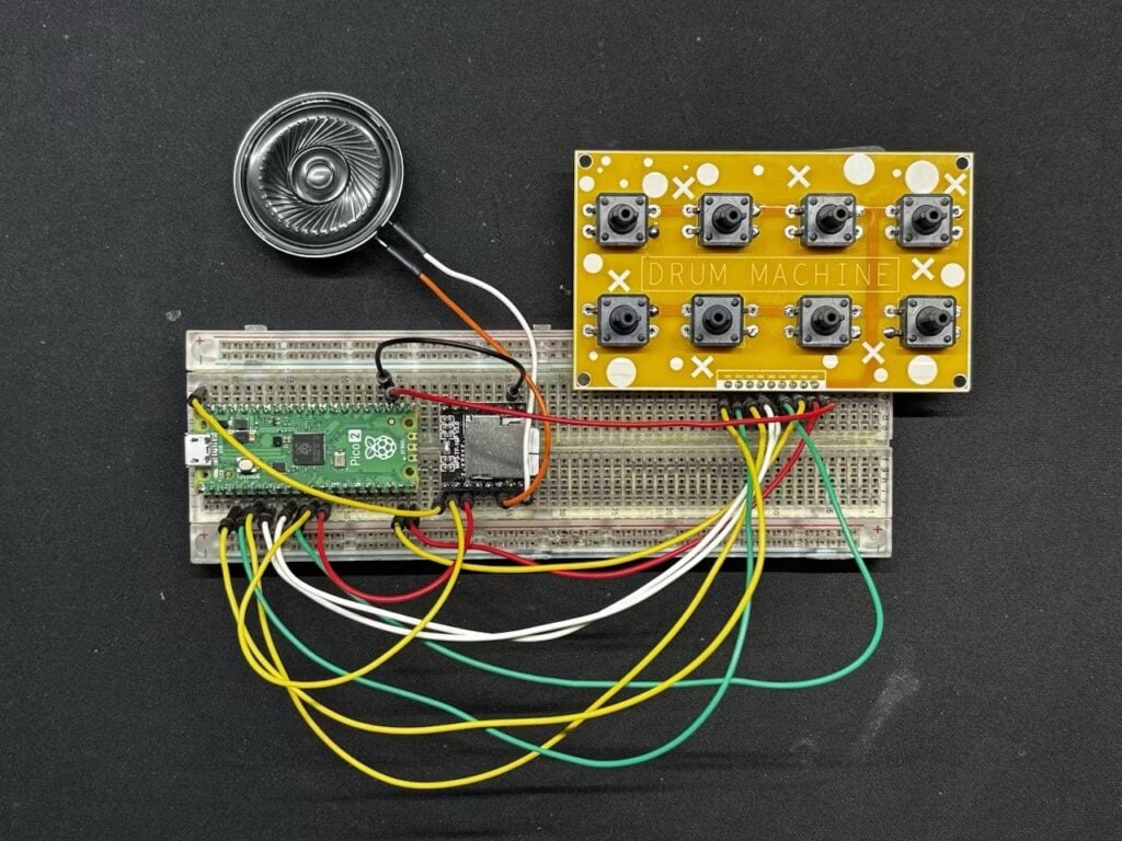
Inspired by Arnov Sharma’s project on Hackster, your author decided to try to create a Pico-powered drum machine using a DF Mini Player to play the drum samples. While Arnov’s version uses a custom PCB for the buttons, we decided to keep it simple with a breadboard-based design — the downside being the spaghetti of jumper wires needed to connect everything up. Still, the principle is the same: you press different push buttons to trigger different drum samples on the DF Mini Player, outputting the audio to a mini speaker.

Building the circuit

To make it easier to wire the buttons to our Raspberry Pi Pico, we opted to put them on a second half-size breadboard, as you can see in the wiring diagram (Figure 1). Each four-legged button spans the division in the middle of the breadboard, with the pins on one side connected to a ground rail. The other side of each button is connected to a GPIO pin on Pico — we used GPIO 28, 27, 26, 21, 20, and 19 — that is pulled up (in the code). So when you press the button, the GPIO pin is pulled low, and the code senses this and triggers the DF Mini Player to play the relevant sample (more on that later).

Figure 1: The wiring diagram for the Pico drum machine

The DF Mini Player was placed on the same breadboard as Pico, connected via UART RX and TX pins, along with 3.3V power and ground. We used its speaker output pins to connect a mini speaker (ours was 2W, 8Ω).

To play some sounds, we needed some drum samples. There are lots of free, open-source ones available online; we got ours from GitHub. We found that some of the samples were a little long — and the DF Mini Player can only play one file at a time — so we opted to edit them in Audacity. If, after trimming the end of a sample, you find it ends too abruptly, you can always apply a fade-out effect.

A close-up of the buttons; each has one pin wired to the ground rail and one on the other side wired to a GPIO pin on Pico

The microSD card must be formatted as FAT32, so we erased it in Raspberry Pi Imager: select Choose OS > Erase, then Choose Storage and select the card. In addition, the files must be named 0001, 0002, 0003, etc., with the relevant suffix — you can use MP3 or WAV files. As we used the latter, ours were named 0001.wav, 0002.wav0006.wav. We found that it doesn’t matter whether you put them in a folder or not.

Coding it

Unlike Arnov, who programmed his drum machine in C, we opted to use MicroPython. For this, we made use of Stewart Watkiss’ DF Mini Player library. Just download the dfplayermini.py script from there and then, using the Files tab in Thonny IDE, right-click and upload the file to your connected Pico (which already has MicroPython installed). You can then call the library in your programs.

We edited our drum samples in Audacity to reduce the length of some of the longer ones

To make sure our drum samples were playing correctly, we created a program (play_drums_seq.py) to test them in sequence:

from dfplayermini import DFPlayerMini
import time

player1 = DFPlayerMini(1, 4, 5)
player1.reset()

print ("Set SD Card")
read_value = player1.select_source('sdcard')

print ("Set Volume 30")
read_value = player1.set_volume(30)

read_value = player1.query_num_files()
print (f"Num files {read_value}")

for i in range(6):
    print("Play",i+1)
    read_value = player1.play(i+1)
    time.sleep(1)

After importing the libraries, we set up a player1 object to work with UART 1 on GPIO pins 4 and 5. We then reset the DF Mini Player so it was ready to start communicating and selected the SD card as the audio source, before setting the volume — we maxed ours up to 30. Next, we queried the number of files on the card (which should be six) and played each one in turn.

Along with Pico, we placed the DF Mini Player on another breadboard and connected it to a mini speaker

We then adapted this to create our main program, which reads the button presses and triggers the sounds accordingly:

from dfplayermini import DFPlayerMini
from machine import Pin
import time

player1 = DFPlayerMini(1, 4, 5)
player1.reset()

print ("Set SD Card")
read_value = player1.select_source('sdcard')

print ("Set Volume 30")
read_value = player1.set_volume(30)

read_value = player1.query_num_files()
print (f"Num files {read_value}")

# Define GPIO pins for buttons
button_pins = [28, 27, 26, 21, 20, 19]

# Initialize input pins
buttons = [Pin(pin, Pin.IN, Pin.PULL_UP) for 
pin in button_pins]

# Main loop
while True:    
    for i in range(len(buttons)):        
        # Read button state        
        if buttons[i].value() == 0:            
            player1.stop() # stop current sound            
            read_value = player1.play(i+1)         
        time.sleep(0.01) # Debounce delay

Here, we added a line at the top to import the Pin method from the machine library. We created a list to set the GPIO pins for the buttons, then initialised them as inputs with the pin pulled up. In the main loop, we read the button state and then, after stopping any currently playing sound, played the relevant drum sample. We added a very short debounce delay to prevent a button press causing multiple triggers.

You need to name the files on the microSD card in (four-digit) numerical order for the DF Mini Player to recognise them

Hands up: the performance wasn’t as good as we’d hoped, with a noticeable lag between pressing a button and the sound being played. As already mentioned, the DF Mini Player can only play one file at a time, which is a major limitation for a drum machine. An alternative would be to use an I2S-based audio board, such as the Waveshare Pico-Audio, to play the drum sounds. Still, our little Pico drum machine does work, and you could use it to trigger other samples, such as spoken phrases or funny noises. Alternatively, using four of the buttons, you could try out Stewart Watkiss’ MP3 player project to play songs stored on the microSD card. 

Raspberry Pi Official Magazine #155 out NOW!

You can grab the latest issue right now from Tesco, Sainsbury’s, Asda, WHSmith, and other newsagents, including the Raspberry Pi Store in Cambridge. It’s also available from our online store, which ships around the world. And you can get a digital version via our app on Android or iOS.

You can also subscribe to the print version of our magazine. Not only do we deliver worldwide, but people who sign up to the six- or twelve-month print subscription get a FREE Raspberry Pi Pico W!

The post Raspberry Pi Pico–powered drum machine appeared first on Raspberry Pi.


from News - Raspberry Pi https://ift.tt/NhReyc3

Monday, June 23, 2025

Atari 2600 digital photo frame

This #MakerMonday, we learn how to display photos as blocky 8-bit masterpieces on a classic console with the help of Raspberry Pi Pico. You can find more projects like this in the latest issue of Raspberry Pi Official Magazine.

The Atari 2600 is an iconic console dating back to 1977. But it’s also a machine that is notoriously difficult to program due to its simple, limited hardware. There’s no character ROM, no frame buffer, and only 76 CPU cycles per scan line. What’s more, the console has just 128 bytes of RAM. And yet, for Nick Bild, this is merely a challenge.

The Picotari cart stores lots of data in the 2600’s tiny address space; the Atari program and image data is copied into Raspberry Pi Pico’s firmware

“I enjoy pushing this kind of hardware to do things it was never intended to do — things that may not even seem possible to most people,” he says. So while, on the face of it, a digital photo frame program doesn’t sound like a big deal, it’s actually mightily impressive.

Pixel placement

Nick’s program allows photos that have been converted into 8-bit pixel art to be displayed as a slideshow. However, since Atari 2600 cartridges can only contain 4kB of data (or 64kB if they’re bank-switched), he needed to get creative. 

To that end, he’s built what he calls a Picotari cartridge, with an edge connector that can slot into the console’s cart port. It supports a Raspberry Pi Pico microcontroller board, which provides two key benefits: it adds extra memory for storing many images and enables the running of his customised Atari 2600 ROM emulator so that the hardware can make use of them.

The prototype cart’s breadboard and perfboard caused electromagnetic interference

The Digital Photo Frame program is then able to display each of those photos, in turn, as a 64×84 pixel image. In doing so, the program is fooling the Atari into thinking only one byte is being used for each picture — it’s addressing a specified byte each time another eight pixels are needed to draw a player sprite. Nick uses a trick that employs sprite copies and vertical delays to fit six 8-bit sprites on a single line (giving 48 pixels in total) before drawing another two sprites (an extra 16 pixels) straight after. 

“The Atari asks for the data at a given address, and the Pico returns the data that is stored at that address, just like a physical ROM chip in an old cartridge would do,” he explains. “But when a special address is requested, the Picotari sequentially returns data from a special storage area outside of what the Atari can normally access. In this way, image data can be supplied byte by byte, right as it is needed, to draw the images.” 

Bit manipulation

For it to work, the images need to be prepared in advance. This is done on a PC using a JavaScript library, Pixel It, with touch-ups from the GNU Image Manipulation Program. 

The custom PCB slots directly into the Atari 2600 cartridge port

“Aside from lacking in storage space, the Atari is severely constrained in terms of processing power, so the images need to be fed to it in a simple data structure that can drive the display with as few instructions as possible,” Nick says. “I experimented with a few tools to give the images the right 8-bit look at a low resolution, then wrote some scripts to prepare the data structures that were to be loaded onto the Pico.”

The result is a unique app that truly pushes the hardware to produce instantly recognisable pixel-based photos, and Nick has been so inspired that he’s now thinking about creating something like a Game Boy Camera for the system. Not that this will be any easier: “The severe hardware constraints of the Atari make for difficulties every step of the way,” he says.

The post Atari 2600 digital photo frame appeared first on Raspberry Pi.


from News - Raspberry Pi https://ift.tt/1qEOMPi

Friday, June 20, 2025

New cohort of Cornell students turn in their Pico projects

Hunter Adams is a lecturer in electrical and computer engineering at Cornell University who has written his Digital Systems Design Using Microcontrollers course around RP2040. He gets in touch regularly to show us all the innovative gubbins his latest cohort has made, and this past semester delivered no fewer than 40 Raspberry Pi Pico–based projects.

Here’s a handful of our favourites:

Robot dog

Cucumber the robot dog can do the downward dog pose better than most yoga instructors. Cucumber is a Wi-Fi–controlled quadruped that follows you around, poses on command, barks, and displays personality.

Sisyphus sand table

This Sisyphus-inspired sand drawing table is more of a kinetic sculpture than a piece of furniture. It creates intricate patterns by dragging a steel ball through sand using a magnetic system beneath the table’s surface. This project caught our eye as it reminded us of Sisyphus Industries’ Raspberry Pi–powered works of art.

Pico-Fight video game

We absolutely love the hand-generated art in this video game called Pico-Fight. It’s a strategic two-person combat game inspired by the open source fighting game ‘Footsies’, and the sound effects and the artwork give just the nostalgia hit we needed.

Drawing robot

Linus the drawing robot is a 2D-drawing machine that uses a marker to draw inputted images in the line art style.

Audio localisation

And finally, for this impressive audio localisation project, students created a $20 acoustic camera that transforms sound delays into visual heat maps, revealing where noises originate in real time.

You can find a YouTube playlist full of student demonstrations for all 40 projects here, and a link to all their project webpages if you’d like to learn more about how they were made here.

Learn along with Cornell students

Hunter has also updated all of his lectures, and they’re available here for those who’d like to experience a taste of learning at Cornell University. These have expanded considerably since Hunter started teaching this course, and now include Raspberry Pico W content (like making Bluetooth servers, connecting to Wi-Fi, using UDP communication, etc.). They also include some fun lower-level stuff (the RP2040 boot sequence, how to write a bootloader), and some really interesting algorithms (FFTs, physics modelling, etc.). Something for everyone.

We’ve become firm friends with Hunter, and we’re always reminded of the rapid passage of time when he gets in touch each year to show us the latest slew of weirdly wonderful Raspberry Pi–powered creations by Cornell’s electrical engineering cohort. Blink and you’ll be reading the 2026 version of this blog. Hope you had a nice Christmas.

The post New cohort of Cornell students turn in their Pico projects appeared first on Raspberry Pi.


from News - Raspberry Pi https://ift.tt/RDTESfo