Wednesday, June 18, 2025

Numitrons, Nixies, and numeric displays

There’s something charming about the clash between obsolete and modern technology. I hadn’t heard of Numitron tubes until a few months ago (when I watched this video by Alec from Technology Connections), but I’ve been looking for an excuse to make something with Nixie tubes for a long time now, as they’re such a unique way to display data.

While the glow and the general tubiness of the Nixies and Numitrons look similar, they rely on quite different technologies. Nixies came first, arriving on the scene in the mid-1950s. Known more formally as cold-cathode displays, they use the same physics as neon lights to produce their glow. The tubes typically contain a series of stacked cathodes shaped to form the numbers zero to nine, with a mesh grid at the front that serves as the anode. When a relatively high voltage (typically around 170V DC) is applied on one of the cathodes, the neon inside the tube becomes ionised. The free electrons now flowing through the tube collide with the neon atoms that occupy the tube, transferring the kinetic energy of the free electron to one of the electrons orbiting the atom and pushing it into a higher, less stable energy level. When those electrons collapse back to their stable state, they emit a photon, giving the Nixie a warm orange glow.

Numitrons, while a later development, use a much simpler technology to display their numbers: the humble lightbulb filament. While Numitron tubes were quickly superseded by lower-current, more reliable LED seven-segment displays, for a brief period they offered a safe, low-voltage (about 5V) alternative to the Nixie tube.

Numitron clock

The first circuit I designed with the Numitrons was a small clock, about the size of a Raspberry Pi Zero/Zero 2 W. The first iteration used a pre-production version of RP2350, which had been left to gather dust in my desk drawers for a few months after being used for testing early last year. Joining RP2350 were a handful of BCD to seven-segment drivers (CD4511BEs), which had a couple of advantages: they reduced the number of GPIOs I needed to use and produced a relatively high output current. Each Numitron segment within the IV-9 tubes consumes about 20mA, which, when summed together, would exceed what most microcontrollers can handle — but poses no problem at all for the CD4511s.

The first version used the same 3.3V supply for the decoders as for RP2350, which gave a somewhat dim glow; the IV-9 tubes are rated for 4.5V, so this left them noticeably underpowered. Later board revisions swapped the 3.3V supply to the tubes for a 5.1V supply directly from the USB socket, which gave a much stronger light, albeit with a potential reduction in lifetime and the added requirement for level shifters between the microcontroller and the tube drivers.

From the second revision onwards, I decided to switch to RP2040 (this was in the days before RP2350 became available via JLCPCB’s PCB assembly service). Other upgrades over the four generations of Numitron clock have included augmenting the crystal with a temperature-controlled crystal oscillator (TCXO) on one of GPIO pins (reducing the maximum error time from 15 to 2.5 minutes per year) and adding brightness control via PWM. This increases the clock’s lifetime by reducing the maximum temperature reached by the filaments and enables it to be used comfortably both day and night.

Numitron calculator

After learning a lot through my experiments with the clock, a calculator seemed like an interesting step forwards and a chance to try out a couple new things. The basic process for displaying a number is much the same as on the clock: a microcontroller outputs a binary number, which goes through a level shifter, into a BCD to seven-segment driver, then onto the Numitron — only this time, we have a lot more tubes. With seven Numitrons, this circuit requires 28 GPIOs to drive the decoders, which doesn’t leave any space for an input from the user, nor for additional outputs to the decimal points on the IV-9 tubes if using an RP2040. However, RP2350 comes in a new 80-pin package variant, with a massive 48 GPIOs exposed — which was just as well, as I used every single pin available.

I also wanted to try OSHPark’s After Dark PCB service, which uses a black substrate and clear solder mask, leaving the copper traces visible. To provide the input, I used mechanical key switches for a very tactile feel, with brown keycaps to match the circuit board. I also designed a simple case for the calculator, which was expertly 3D-printed by our Maker-in-Chief (thank you, Toby!).

As with the clock, I used the pico-sdk to write some code to poll the input, drive the display, and crucially crunch the numbers inputted. The calculator handles decimals with ease, but due to a small oversight in its design, it has no way of displaying negative numbers.

Nixie clock

The final project was to try to make a Nixie clock. This was the first project I’ve worked on with a high voltage, so to give myself a small advantage (and to avoid electrocuting myself), I used a pre-made module to convert between the USB’s 5V and the required 170V.

The rest of the clock circuit followed a similar form to the Numitron clock, with a TCXO providing an accurate time base and specific Nixie drivers taking the place of the BCD decoders.

I did have some trouble getting the Nixies to work on my first circuit board. I tried everything to get them to work correctly, like soldering up a new board, replacing components, and so on, before eventually realising I had the wrong driver chips (I’d bought K115ID1 chips instead of the correct K155ID1 ICs). Once these were replaced, things looked significantly better, but the numbers on the Nixies kept showing the wrong values. This was because I’d misread the datasheet for the IN-12 tubes I was using and had put the footprint for the tubes upside down in my design. One board re-spin later, it finally worked!

Because of the high voltage, I wanted to make sure that the PCB was safely enclosed in a case, which, to create a bit of a brutalist look, I decided to make out of cement. The first step was to 3D print a couple of moulds, one for the back of the case, which would have the cement set around four standoffs to mount the circuit board, and the other to provide the sides of the enclosure. A day after pouring the cement and placing the standoffs within it (with the help of a spare board), the case, and the clock, was ready.

Thank you to Lloyd and Toby for their help with the mechanical design/building, and to Alfie for his translation of the IN-12B datasheet.

The post Numitrons, Nixies, and numeric displays appeared first on Raspberry Pi.


from News - Raspberry Pi https://ift.tt/zuR7SYy

Monday, June 16, 2025

Learning with a homemade model insulin pump

This #MakerMonday we learn about a Raspberry Pi-based medical pump made by a diabetic teen who wanted to understand how insulin doses keep him alive. You can find more projects like this in the latest issue of Raspberry Pi Official Magazine.

Teenager Rune Bobbaers was diagnosed with the auto-immune illness type 1 diabetes before he was old enough to start school. Curiosity about how insulin is used to manage his glucose levels and keep his body in check led Rune to investigate how to create his own dosage pump so he could understand how it operates. He was “immediately hooked” as soon as he began using Raspberry Pi 400. “That such a small, affordable computer could do so much really inspired me.” He worked on what would become his IINTS insulin pump project during CoderDojo sessions learning MicroPython and using Raspberry Pi Pico W. The now 16-year-old Rune submitted it as a Coolest Project, where it immediately caught the eye of the Raspberry Pi Foundation’s judges. 

The IINTS open-source insulin pump has a stepper motor to control its syringe. The Raspberry Pi Pico W setup has an on-screen insulin dose indicator and manual selector buttons.

Mastering making

Rune was keen to design and build a fully open-source insulin pump from scratch having long “been fascinated by the medical technology that helps keep me alive, especially insulin pumps”. There was never an intention to produce a certified medical product. Instead he was after a personal learning experience as his curiosity gradually turned into a deep interest in technology and programming. Through his local CoderDojo group in Brussels, he’s had “the opportunity to turn ideas into real projects, ask questions, and get support from amazing coaches”. With a few Raspberry Pi builds under his belt, Rune credits the CoderDojo coaches’ support with giving him the confidence to tackle his first full project that combines hardware, software, mechanics, and medical tech all in one.

Rune set about recreating a pump simply and with affordable components. He chose to use MicroPython and Raspberry Pi Pico W because “it’s compact, affordable and powerful enough to handle everything from motor control and display updates to button input and background logic”.

Rune was fascinated by the medical technology that helps keep him alive

The IINTS pump (the acronym means ‘insulin is not the solution’) can be used to manually select a dose using tactile buttons, with the amount shown on a small display. It can also calculate recommended doses based on a preset insulin-to-carbohydrate ratio. Once the dose is selected, a stepper motor controlled by Raspberry Pi Pico W pushes the plunger of a standard syringe and delivers the insulin. Impressively, Rune has even managed to add a feature whereby a background dose of insulin is continuously delivered, just like the prescription pump he uses to regulate his glucose levels. 

Healthy approach

Rune began simply with a very basic breadboard setup that allowed him to test the screen, buttons, and motor together. Once this was working, he started designing and printing parts to hold the motor and syringe in place. “That’s when the real problems began: one of the early 3D-printed parts seemed slightly misaligned, so I mounted it on a metal lathe to try and fix it,  only to later realise the issue wasn’t with the printed part at all, but with the stepper motor driver! Undeterred, Rune rewrote the code, simplifying large parts of it.  He also had to redesign the enclosure, improving its durability and ergonomics as well as making it less bulky.

Rune confidently shows off his open-source insulin pump at Coolest Projects

Rune has a sanguine approach to the iteration process. “Each version solved a problem from the previous one and, with every iteration, I learned something new about mechanics, electronics, and system integration,” he tells us.

“This insulin pump is the result of everything I’ve learned so far – and of my passion for understanding the devices that have such a big impact on my life.” He’s already planning the IINTS Mk II and would love to design a custom PCB to clean up the wiring, make the pump more compact and reliable, and make it easier for others to build their own version.

Anyone inspired to do so can check out his excellent video below.

Warning!

Do not use

This project is for educational purposes only. It is not a medically approved insulin pump and should not be used to administer insulin. Consult a medical professional for insulin administration advice.

The post Learning with a homemade model insulin pump appeared first on Raspberry Pi.


from News - Raspberry Pi https://ift.tt/alhbzuH

Friday, June 13, 2025

Sustainable solutions: offsetting our carbon footprint with enhanced rock weathering

At Raspberry Pi, our approach to sustainability mirrors our approach to engineering computers: we look for the most effective solutions at the best price point. This extends to our environmental impact, which is why we’re proud to be using enhanced rock weathering (ERW) technology to offset the carbon footprint of our single-board computers.

Photo showing a tractor spreading crushed rock on a grassy field

Enhanced rock weathering offers a nature-based approach to reducing atmospheric carbon dioxide (CO₂); it does this by significantly accelerating the Earth’s natural silicate weathering process. This geological process typically occurs over thousands of years as rainwater, slightly acidic from dissolved atmospheric CO₂, reacts with silicate rocks. During this reaction, CO₂ is chemically locked away in stable forms like carbonates and bicarbonates before eventually flowing into oceans or forming mineral deposits on land, effectively removing it from the atmosphere.

How we UNDO our carbon emissions

Earlier this year, we partnered with UK-based climate science company UNDO Carbon, pioneers of enhanced rock weathering technology. UNDO’s ERW solution involves spreading finely crushed silicate rock, such as wollastonite, across agricultural land. By increasing the surface area of the rock through crushing and then integrating it into active agricultural soils, the rate of chemical reaction with atmospheric CO₂ is greatly enhanced. This method not only sequesters atmospheric CO₂, but also offers additional agricultural benefits by boosting soil health and crop yields.

“Working with forward-thinking organisations like Raspberry Pi is incredibly important to us,” says Chris Zair, Head of Partnerships at UNDO. “It demonstrates a shared vision for a sustainable future and helps us to scale our efforts in removing carbon for good.”

The Intergovernmental Panel on Climate Change (IPCC) suggests that, if scaled, ERW could remove up to 4 billion tonnes of CO₂ annually, achieving a very substantial 40% of CO₂ removal targets. UNDO’s operational model takes advantage of existing infrastructure, enabling the company to scale its operations quickly and offer carbon removal at competitive prices. As UNDO’s model leverages existing infrastructure and the rock is spread locally, its operations boast a carbon efficiency greater than 90%.

Aerial photo showing a tractor spreading crushed rock on a field
Silicate rocks are the most abundant on Earth, meaning ERW has the potential to rapidly scale and permanently remove billions of tonnes of carbon dioxide every year

UNDO’s recent success in the XPRIZE Carbon Removal competition is a testament to their scientific rigour and the potential scalability of their ERW technology. This four-year, $100-million initiative is the largest incentive in prize history, designed to encourage the development of more scalable, durable, and sustainable CO₂ removal solutions. From a field of over 1300 applicants from 88 countries, UNDO emerged as third-place runners-up, securing a $5 million share of the prize.

The finalists were challenged to remove over 1000 net tonnes of CO₂ from the atmosphere. Independent verification bodies confirmed that UNDO successfully removed 1209 tonnes of CO₂ as part of their operations in Canada, where they used fast-weathering wollastonite. Jim Mann, founder and CEO of UNDO, highlighted the win as a powerful validation of their scientific approach and massively scalable operational model. The prize money will further enable UNDO’s research and development, helping to reduce the cost of carbon removal and make their solution even more accessible.

Product image of Raspberry Pi Carbon Removal Credits
We released our Carbon Removal Credits alongside the 16GB variant of Raspberry Pi 5 earlier this year

Investing in a greener future

By partnering with UNDO Carbon and embracing ERW, Raspberry Pi is making an active commitment to innovative and effective sustainability practices. Each Raspberry Pi Carbon Removal Credit contributes to UNDO’s carbon removal work, which, over time, will help to remove CO₂ from the atmosphere; once verified, each credit will offset the manufacture, shipping, and disposal of one of our single-board computers, allowing you to contribute directly to these impactful carbon removal efforts. We take our responsibility to look after the planet seriously, so we’re not just talking about a greener future; we’re actively investing in and supporting the technologies that can make it a reality.

The post Sustainable solutions: offsetting our carbon footprint with enhanced rock weathering appeared first on Raspberry Pi.


from News - Raspberry Pi https://ift.tt/K8vfW3k

Monday, June 9, 2025

Detect radio jammers with Raspberry Pi 5

For #MakerMonday this week, we’re diving into the pages of the latest issue of Raspberry Pi Official Magazine, where we find Signal Sentinel – a great research project that harnesses Raspberry Pi 5’s ability to detect radio jammers.

Cybersecurity gets plenty of media coverage, not least because most of us have become so dependent on electronic communication and internet connectivity that disruptions can cause major havoc. In splat-a-rat fashion, one type of threat gets beaten back, only for another to rear its head.

An ML-trained 4GB Raspberry Pi 5 analyses real-time traffic provided by an RF-SDR dongle

Solent University final-year student Josh Perryman reasoned that focusing his efforts on identifying a specific type of cyberthreat would be a practical use of machine learning, and also make a great excuse to finally try Raspberry Pi’s capabilities in this field for himself. His Signal Sentinel can detect jamming attacks on wirelessly connected devices including IoT hardware and even cars – an increasingly prevalent target for thieves. Josh envisages his Signal Sentinel being integrated with other systems which mitigate or prevent the attack.

Demonstration model

Having trained and worked for a decade as a chef, Josh says he “didn’t have much of a technical background, just some basic Arduino robotics projects” and a Raspberry Pi weather station build as part of his course. However, he was interested in embedded systems and IoT, had always wanted to build a project using Raspberry Pi and his final-year project gave him the perfect excuse. 

Some signal jammers are sold as kits hidden in flight cases; Signal Sentinel is designed as a portable setup to detect them

The plan was to get Raspberry Pi to classify and passively detect radio frequency jamming signals. Josh would build a proof-of-concept model to demonstrate how effectively and efficiently machine learning could be used for the purpose. He selected Raspberry Pi 5 for its processing power and with an eye on planned future projects involving the AI+ HAT and Camera Module NoIR. Keen to keep build costs down, he began with an unbranded LCD that seemed to have similar capabilities to Waveshare’s. However, Josh soon found out that this was a false economy: “the unbranded screen was quite cheap and caused some electrical issues, causing Raspberry Pi to turn off when [it] was connected. Changing this for a better-quality screen fixed this issue.

Perfect fit

The Signal Sentinel was easy to build, with little call for custom parts (he bought most items from The Pi Hut, where he is a regular customer) and a flight case that could house all the components. Next, Josh mapped out areas where the RTL-SDR dongle could fit through when in use. This was critical since it would provide live radio transmission data. He also carved a channel into the case’s foam lining for the power cable, plus sections to snugly house the Waveshare screen, keyboard, and Raspberry Pi 5.

As a confident Python coder with experience of using MQTT, Josh’s main technical challenge for the RF jammer was collecting a diverse enough database. It needed to include “a good variety of jamming signals and ‘safe’ signals such as background noise, key fobs, RF devices, and radio stations”. Collecting sufficient data accounted for the large majority of the four-month project. The hardware build took only a few hours. 

Remote unlocking has left cars vulnerable to theft using RF jammers, the Perfect Jammers website warns

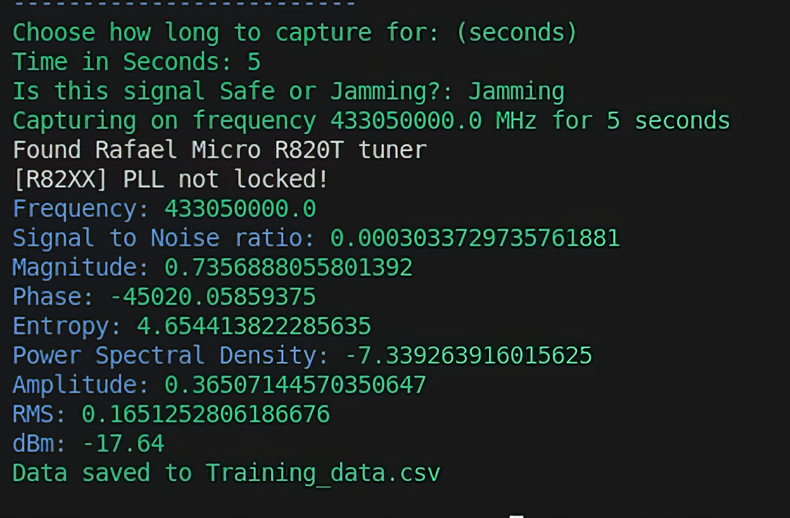
Josh used Ubuntu VM on his laptop for data collection, prototyping, and testing. Once he was satisfied that his machine learning models were effective, he created a simple terminal interface for the Signal Sentinel in Raspberry Pi OS and attached a miniature keyboard. The main menu monitors whichever frequency is selected by the user, while a smaller LCD indicates whether the airwaves are currently ‘safe’ or ‘jamming’, based on the model’s prediction. 

Building experience

Although the SDR dongle worked well, Josh suggests someone with a keen interest in radio wanting to replicate his build might prefer the better bandwidth and range offered by a HackRF One or Pluto SDR, though these are larger and not necessarily ideal for fitting inside a small flight case. However, the Signal Sentinel is best used in a lab environment where jamming signals can be contained to prevent accidental interference. Having submitted his final dissertation, Josh intends to refine his model “to detect jamming attacks which aren’t just noise and signal blocking, but more sophisticated attacks which would otherwise go unnoticed in their current stage”.

Download and install Josh’s dataset and code from his GitHub page

Warning!

This project is for detection only.

The use of RF (radio frequency) jammers in the UK is strictly prohibited under the Wireless Telegraphy Act 2006. Other laws and regulations may apply elsewhere in the world.

The post Detect radio jammers with Raspberry Pi 5 appeared first on Raspberry Pi.


from News - Raspberry Pi https://ift.tt/lydZT9z

Friday, June 6, 2025

Build a Raspberry Pi classifier: detect different Raspberry Pi models

In part one of this new tutorial series, you can learn how to use a Raspberry Pi AI Camera to detect different Raspberry Pi models. This series was created by David Plowman, an engineer at Raspberry Pi with a special interest in image processing hardware, as well as camera software and algorithms.

In this tutorial, we’ll use a Raspberry Pi AI Camera with a pre-trained model to detect different Raspberry Pi computers. You’ll be able to point your Raspberry Pi AI Camera at a Raspberry Pi 4 and see ‘Raspberry Pi 4’ displayed on the screen, or ‘Raspberry Pi Zero’ for a Raspberry Pi Zero, and so on.

Raspberry Pi AI Camera attached to a Raspberry Pi 5

This is a powerful example of how Raspberry Pi can be trained to perform real-time inference of object detection. It’s a good way to explore the Raspberry Pi AI Camera API (application programming interface) and the relationship between models and inference.

Set up your AI Camera

Connect your Raspberry Pi AI Camera to a compatible Raspberry Pi computer. We are using a Raspberry Pi 5, but the AI Camera is compatible with all Raspberry Pi models. You can read the AI Camera datasheet for more information.

The Raspberry Pi AI Camera features a Sony IMX500 image sensor that provides low-latency, high-performance AI capabilities to camera applications without needing an AI HAT+ (or AI Kit). It runs custom neural network models on the IMX500 sensor.

Raspberry Pi AI Camera contains a Sony IMX500 sensor with AI inferencing ability

Make sure your Raspberry Pi is up to date, then install the IMX500 firmware:

$ sudo apt install imx500-all

This command: 

  • Installs the /lib/firmware/imx500_loader.fpk and /lib/firmware/imx500_firmware.fpk firmware files required to operate the IMX500 sensor
  • Places a number of neural network model firmware files in /usr/share/imx500-models/
  • Installs the IMX500 post-processing software stages in rpicam-apps
  • Installs the Sony network model packaging tools

Now reboot your Raspberry Pi:

$ sudo reboot

Let’s test if it’s all working. The following command runs rpicam-hello with object detection post-processing:

$ rpicam-hello -t 0s --post-process-file/usr/share/rpi-camera-assets/imx500_mobilenet_ssd.json --viewfinder-width 1920 --viewfinder-height 1080 --framerate 30

The following command runs rpicam-hello with pose estimation post-processing:

$ rpicam-hello -t 0s --post-process-file/usr/share/rpi-camera-assets/imx500_posenet.json --viewfinder-width 1920 --view

Get the code

Now that your AI Camera is set up, you’ll need the code. For this tutorial, it’s best to start by copying the files from GitHub. In terminal, enter:

$ git clone https://github.com/davidplowman/pi_classifier.git 

Enter the pi_classifier directory and take a look inside:

$ cd pi_classifier
$ ls

Here you will find three files:

  • demo.py — the Python code file
  • labels.txt — a text file containing the labels for different Raspberry Pi models
  • network.rpk — a ‘runtime package’ file trained to detect Raspberry Pi models using the Sony IMX500 image sensor

Run the code with Python:

$ python demo.py

A preview window will appear on the screen, displaying the view from the AI Camera. Hold a Raspberry Pi up in front of the camera, and the preview window will display the model corresponding to the options in the labels.txt file. 

How it works

Let’s open up the demo.py code in Thonny (or a code editor of your choice) and take a look at it:

$ thonny demo.py

parse_and_draw_classification_result

This function is given to the camera system as a callback function, meaning it gets called automatically every time a new frame arrives from the camera without us (the application) having to do anything extra. Because we’re using the Sony IMX500 sensor, we get not only the usual camera image but also an output tensor listing the results of running the neural network on the image.

We need to parse the neural network results using parse_classification_result, then draw them onto the camera image using draw_classification_result.

parse_classification_result

This analyses the output tensor produced by the IMX500 sensor and decides if the image belongs to one of categories that the network was trained on. There are a couple of things to watch out for.

Detecting a Raspberry Pi 3

Firstly, there isn’t always an output tensor. This can happen if the neural network accelerator didn’t quite finish processing the frame in time. When this happens, we should just reuse the result from the previous frame; another frame, where the tensor is once again available, will be along shortly!

Next, we return the category with the highest confidence value. Some networks may tell us that we should apply a softmax operation to the output values to get a more realistic probability for each class.

draw_classification_result

Here we draw a label on the camera image indicating the device category and confidence value — but only if the confidence value is sufficiently high.

We get access to the actual camera image pixels (not a copy of it) in the usual way, using Picamera2’s MappedArray. We measure the size of the box that the category label and confidence value will occupy, then darken that part of the image so that the text will stand out better when we subsequently write it on top.

Detecting a Raspberry Pi Zero

if __name__ == “__main__”

This section of the code is simply concerned with configuring the IMX500, uploading the neural network firmware file (network.rpk), and getting the camera running. There are just a few things to point out:

  1. We first create the IMX500 camera helper object. This will upload the network for us, and also tells us which camera number the IMX500 is.
  2. The NetworkIntrinsics object is a helper for the network that will recommend an appropriate frame rate we can use, which should match the inference rate of the network on the IMX500.
  3. Before starting the camera, we should tell the IMX500 helper that we would like to see a progress bar for the network upload — otherwise it’s easy to think it might have got stuck! Recall that the network firmware uploads more quickly on subsequent occasions, as more of the firmware blocks are already cached within the device.
  4. Finally, we let the script run forever, and all the camera processing happens in background threads.

Download the full demo.py code for the Raspberry Pi Classifier.

The post Build a Raspberry Pi classifier: detect different Raspberry Pi models appeared first on Raspberry Pi.


from News - Raspberry Pi https://ift.tt/lwrh8CX

Wednesday, June 4, 2025

CyberPi: Cyberpunk-inspired dashboard based on Raspberry Pi 4

Mike (aka Dream in Digital) is a big fan of the gritty, high-tech, Cyberpunk vibe. Mike is also a nerd, so rather than, I don’t know, just having a quick play of the video game to immerse himself in the fictional metropolis of Night City, he decided to pour his blood, sweat, and tears (his words, not mine) into building his own Cyberpunk-style dashboard.

Kit list

What does it do?

CyberPi is powered by a Raspberry Pi 4 running Raspberry Pi OS. It has a shiny neon HUD interface that displays the system’s stats. Mike also integrated music streaming and scrolling news functions into the dashboard, along with a YouTube subscriber counter. Despite not feeling confident with Linux-based programming languages, he was able to lean on ChatGPT to help him create the dashboard from scratch. He also managed to turn the device into a Roon endpoint, enabling him to stream music straight from his Roon Core while out and about with CyberPi.

The hardest part of the build for Mike was setting up the ultra-wide screen and fixing the display resolution. After fiddling for the better part of a day and failing to find any instructions online, ChatGPT came to the rescue again to get this part of the project over the line.

System stats

The inspiration for the look and feel of the display came from the “glowing teal” of Cyberpunk control rooms. Mike wanted it to feel like the device is “always breathing”, even if he isn’t using it for anything in particular. This was achieved by dedicating display space to live graphs of the Raspberry Pi’s RAM and GPU usage, as well as the system’s temperature, and overlaying these on a slowly moving grid background.

The upper-right quadrant shows the Dream in Digital YouTube account‘s subscriber total going up; the bottom left displays what music is currently playing, and the bottom right is Mike’s curated RSS news feed.

Versatile tech

CyberPi isn’t the first iteration of all this tech; Mike previously used it to make a music streamer running on Volumio software. You can watch him build it over on his other YouTube channel, Audio Arkitekts.

The post CyberPi: Cyberpunk-inspired dashboard based on Raspberry Pi 4 appeared first on Raspberry Pi.


from News - Raspberry Pi https://ift.tt/LuaBI25

Monday, June 2, 2025

Raspberry Pi 5 ‘Pepper Pi’ transparent computer illusion

Raspberry Pi fans with multiple models will relate to the rationale behind the origins of the transparent computer. This community project comes fresh from the pages of the latest issue of Raspberry Pi Official Magazine. Happy #MakerMonday!

Documenting quirky makes comes naturally to creative couple Martin and Vanessa. Collectively known as Veeb, they’ve been making madcap designs accompanied by fun videos of each build for the past five years. Their latest project, Pepper Pi, makes use of a headless Raspberry Pi 5 they had available to recreate a Victorian illusion known as Pepper’s Ghost, in which an object appears to float in a glass dome. The project also has its roots in early 1900s stock tickers. Impressively, Pepper Pi functions as a perfectly usable transparent PC, too.

Pepper Pi recreates a Victorian mirror illusion in which an image appears to float

Seeing is believing

Originally conceived during lockdown, Veeb’s videos soon caught on (and meant they didn’t need to do quite so much worthy documentation!). Imitation is flattering, and when Martin and Vanessa realised other people enjoyed some of the videos they’d made combining old tech with new to create their own versions, they embarked on an ongoing series. “We started to hear about people reproducing what we’d done. That felt good and was enough to make us keen to keep sharing projects whenever we thought we’d done something vaguely interesting.” Veeb now have quite a following — 11,500 subscribers according to their YouTube follower clock.

The day-to-day business involves custom builds that “reimagine vintage design for contemporary living,” Martin tells us. “The Pepper Pi project was prompted by the fact that there are headless Raspberry Pi computers dotted about our office taking care of various tasks.”

Although “ever so useful”, a scattering of hardware components doesn’t produce quite the contemporary finish to their aspirational design studio that, say, scatter cushions or artfully placed houseplants might. Instead, the aim was to spruce things up and turn a selection of “Raspberry Pi computers into interesting things to look at.”

1920s ticker tape machines and Victorian illusions inspired this build, as Veeb’s video explains

Old hands

Martin and Vanessa have many Raspberry Pi builds under their belts. Here, they used a Raspberry Pi 5 to run the statistical package R: “we wanted to use something meaty for number-crunching”. However, the illusory effect with the screen could be done using “more modest hardware” — they have since created one using Pico. A previous project involving an old Super 8 video viewer showed them the potential of lower-resolution screens and how to make the most of them. They still use the Boostbox cyberdeck daily. As with the Pepper Pi project, it combined “a redundant bit of technology and something box-fresh.” 

The duo had fun seeing what they could make appear inside the glass dome

Their take on the 150-year-old Pepper’s Ghost illusion involves a pair of mirrors bouncing a hidden image to make it appear within a transparent dome they bought online. They had seen versions hidden in arcade cabinets, but managed to work out the trickery for themselves. It took a while before they hit on the idea of using a privacy screen to shield the image so it was not on obvious display. In Vanessa and Martin’s version, the source image is hidden behind an acrylic disc that they commissioned “a nice man in Germany” to laser cut. 

To the uninitiated, the dome simply looks like quirky desk furniture rather than a transparent PC

Originally, they set the viewing angle for the mirror to 45 degrees, but soon realised this didn’t work well for viewing the illusion when the Pepper Pi was sat on a desk and in use as a PC. Since the angle of the reflector is pretty important, Veeb created a shape calculator to assist anyone keen to recreate the project. 

With the trigonometry taken care of (and an optional screen attached), they ended up with “a functional computer that has a nice steampunk vibe.” You can even run it as an ornament that can act as a server while intermittently playing that hologram message Princess Leia sent via R2-D2. Martin fervently hopes someone will actually do this.

The post Raspberry Pi 5 ‘Pepper Pi’ transparent computer illusion appeared first on Raspberry Pi.


from News - Raspberry Pi https://ift.tt/XvYBl7J

Thursday, May 29, 2025

Raspberry Pi does the heavy lifting in this elevator simulator

In the brand new issue of Raspberry Pi Official Magazine, David Crookes takes a look at this uplifting replication of an elevator system.

Life can be full of ups and downs — and for maker Alan Boris, that can be something to celebrate. After all, he’s a self-proclaimed lover of elevators, having grown to appreciate just how complex these vertical transportation devices actually are. And, when he rode a “very cool” one recently, his tech ambitions rose to another level.

“When you start to think about the design, elevators have a lot of inputs and outputs: buttons, sensors, motors, LEDs, and floor indicators,” he notes. “They may be simple to use, but they hide a lot of complexity behind the scenes — so I created one using Raspberry Pi devices because it seemed like a great programming challenge.”

Now, it has to be pointed out that Alan didn’t crack on with the task of building a real, working elevator for his home. That would be a disruptive endeavour costing many thousands, which is why he decided to produce a much smaller replica instead. To do this, he made use of a Raspberry Pi 4 Model B computer and some Raspberry Pi Pico 2 W microcontrollers. He also created an impressive hydraulic system. “And it was all a lot less expensive than the real thing,” he tells us.

Uplifting concept

The project also scratched an itch. “I was looking to do a project where the Raspberry Pi single-board computer and the Raspberry Pi Pico microcontroller communicated and worked together,” he explains. To that end, he decided he would make an elevator car operating panel and wirelessly connect it to some hall stations, and began to create about half a dozen diagrams on paper to guide him. He wanted it to be possible to call the elevator by pressing either an up or down button on a station — the idea being that there would be one on each of three floors. He would then have the car’s interior panel’s display react in some way when one of its own buttons was pressed.

It’s very much a concept model made purely for fun, but it demonstrates the complexities involved in coding and operating an elevator

“I wanted the [interior car] panel to be similar to an interesting elevator I was in a few months ago, so I knew it would have an LCD display and buttons that had built-in LEDs,” he says. “The elevator also had spoken messages such as ‘watch your step’, so I knew I wanted to add a DAC and amplifier board to the Raspberry Pi 4 Model B computer to support that. In addition to the messages, the elevator’s panel beeped as each floor was passed, and there were dings for the up and down direction notifications. People often don’t notice that most elevators ding once for up and twice for down when they arrive on a floor, and I wanted all of that in my build.”

The hall station panel only needed two buttons for up and down, but Alan needed a way to show which floor the elevator car was on and the direction it was travelling in. “I searched for a suitable LED matrix display,” he says, “and the buttons were inspired by a different elevator system, so you could say my setup was beginning to be an amalgam of elevator controls I’ve admired over the years.”

Pushing his buttons

Selecting the parts was a challenge. Alan had to ensure the components, such as the display and the LED matrix, had software libraries that he could easily use, and there was a lot of improvisation as he realised the panel would be full of parts that needed to clear each other. “Substituting a part or moving it slightly could affect other part placements,” he reveals. “For instance, the push buttons are very deep, almost the full depth of the case, so very little, if anything, could be placed behind them.” This meant that finding cases that were the correct size was tricky. “I initially considered 3D printing the entire case, but that would have taken too much time. I could not find a long, rectangular project case in stock for the floor call button assembly, so I ended up bolting two shorter ones together.”

Alan says the elevator car panel is the brains of the system: it contains a Raspberry Pi 4, the floor buttons, an LCD display, and audio output; it runs on balenaOS and communicates with the floor call buttons and a high-voltage board using MQTT over wireless LAN

To make the panels look more like the ones in real elevators, he decided to use sheet metal and stick the button labels on (he printed them white-on-black with a laser printer and stuck them on using double-sided tape). Alan had never worked with sheet metal before, but found it was in stock at a local hardware store. He picked up 0.019-inch (0.5 mm) thick sheets that could be cut with simple shears.

“My interior rectangular cutouts for the display were terrible — very uneven with shards of metal sticking out. I filed them down and hid my poor cuts with a simple 3D-printed frame that snapped onto the cut-out sections.”

On the rise

Since Alan had once seen a hydraulic elevator being repaired, he decided this was the system he’d use. “I created a mock-up showing how they work, but this required me to design a board that could allow Raspberry Pi Pico 2 W’s GPIO header to switch high voltages,” he explains. “But it allowed me to work with a relay board, which was a lot of fun. I like how the tiny Pico can control huge pumps and solenoids.”

Alan used a Raspberry Pi 400 to program the Picos used for the system — including the hydraulics for the elevator itself

With no experience of hydraulics or plumbing, this was a learning curve. “I had to educate myself on the various couplings and fittings to fit the PVC pipes and hoses,” Alan adds. Everything was then brought together using a program written in Python. “It basically waits for button presses via Raspberry Pi 4’s GPIO pins and then takes appropriate action.”

Coding the project was another challenge. “It was soon full of ‘if-then-else’ spaghetti code,” he recalls. He then stumbled upon the elevator algorithm. “It basically states to keep moving in one direction and fulfil all floor requests, then start moving in the opposite direction to serve any remaining requests. I crudely implemented this algorithm using a Python list that the program loops through over and over again.”

The hall panels have Picos inside and run on CircuitPython, which also has a compatible MQTT library; the hydraulics use a Pico 2 W to power relays that allow sufficient water in and out of the system, moving the elevator car up and down

“When there is no activity, the program keeps repeating the current step. Everything happens in a large loop in 4.5‑second intervals. Only the ‘door open’ and ‘door close’ buttons can interrupt a loop. Again, the programming gets complex because you can’t always open the door (like when the elevator is moving or between floors), so the code has to keep track of all of that.”

Luckily, it all worked, and Alan looks at the project with a great deal of satisfaction and even deeper admiration for anyone who has coded an elevator. “This simulation was for just one three-floor elevator,” he says. “I can’t imagine the coding required for a bank of elevators in a skyscraper that have to act cooperatively and efficiently.”

Raspberry Pi Official Magazine #154 out NOW!

You can grab the latest issue right now from Tesco, Sainsbury’s, Asda, WHSmith, and other newsagents, including the Raspberry Pi Store in Cambridge. It’s also available from our online store, which ships around the world. And you can get a digital version via our app on Android or iOS.

You can also subscribe to the print version of our magazine. Not only do we deliver worldwide, but people who sign up to the six- or twelve-month print subscription get a FREE Raspberry Pi Pico W!

The post Raspberry Pi does the heavy lifting in this elevator simulator appeared first on Raspberry Pi.


from News - Raspberry Pi https://ift.tt/rqIJ5ZH

Tuesday, May 27, 2025

Building smarter farming irrigation with Raspberry Pi and IoT

While you and I may be content with waiting until we notice the leaves on our houseplants turning a little yellow before poking a finger in the soil to check if it’s dry, Arad Soutehkeshan, a student from the University of Greenwich, is operating on a different level. As part of the MathWorks Sustainability and Renewable Energy Challenge, Arad designed an intelligent irrigation system, helping to take a meaningful step towards tackling the global water crisis.

It ain’t gotta be pretty, it’s just gotta work

Urgent innovation

As explained in Arad’s build video, The Food and Agriculture Organisation reports that traditional irrigation methods waste up to 60% of the water intended for crops. This isn’t just wasteful — it’s catastrophic in regions already battling water scarcity. Arad wanted to combat this issue and, at the same time, contribute to the emerging smart agriculture market with a low-cost solution using Raspberry Pi and open source IoT (Internet of Things).

For more detailed written instructions, visit the project’s GitHub page

Hardware

Brain: Raspberry Pi 3 Model B+ (with an Ethernet cable for stable connectivity)

Eyes: Raspberry Pi Camera Module 3 NoIR, taking regular snapshots of the plant for time-lapse monitoring

Sensors: Capacitive soil moisture sensor, temperature and humidity sensor, light sensor

Actuators: Water pump controlled by a 2-channel 5V relay

Cress seeds were the foliage of choice for this experiment.

Arad’s system workflow

Visual data and IoT

The Raspberry Pi is controlled via the dataplicity terminal, which keeps scripts running and allows you to check in on them remotely without needing to manually babysit.

Sensor readings — including moisture levels, temperature, humidity, light exposure, and pump activation duration — are all sent to ThingSpeak, a cloud IoT analytics platform. This enables Arad to create compelling real-time dashboards, scatter plots, and even kernel density estimations, such as correlating soil moisture with watering time. Being able to visualise the very clear relationship between existing soil moisture and the decreased need to water plants encourages smarter agricultural practices, potentially preventing astronomical amounts of water wastage.

ThingSpeak is also a proactive system. It checks soil moisture every six hours and fires off an email if sensor readings are outside the healthy range.

Timelapse growth diary

Photos taken by the Raspberry Pi camera are deposited into Dropbox folders with date and time stamps. These are then stitched into a timelapse video, forming a visual diary of growth (and proof that the system works). You can watch as your plants go from over- or under-watered wilts to efficiently thriving members of our ecosystem.

The post Building smarter farming irrigation with Raspberry Pi and IoT appeared first on Raspberry Pi.


from News - Raspberry Pi https://ift.tt/YFISHv7

Friday, May 23, 2025

Navigating global market access: how Raspberry Pi supports OEMs

Bringing a new product to market is never easy, especially when that market is in another country. Each region has its own regulations to follow and certifications to obtain before you can sell or even import an electrical or electronic device; this process, known as Global Market Access (GMA), can quickly become a costly and time-consuming barrier for manufacturers. That’s why Raspberry Pi has developed a comprehensive in-house approvals regime, designed to remove as much hassle as possible for our OEM (original equipment manufacturer) customers, whether they’re using our computers, our microcontrollers, or our compute modules.

What is Global Market Access?

Manufacturers and importers know how challenging it can be to introduce electrical or electronic products into new countries: there are always plenty of barriers, costs, and challenges involved. With very little alignment on compliance requirements around the world, products often need to be re-certified whenever they enter a new market.

The process of gaining product compliance approvals can be complex, with GMA requirements differing to varying degrees depending on where you are or where your product is going. Compliance procedures can range from as little as submitting application paperwork to government agencies and certifiers (like South Africa’s ICASA or Thailand’s NBTC) to as much as full-scale, in-country testing of the product itself (as required for SRRC approval in China or ANATEL approval in Brazil).

Image showing an underwater navigation device by company Blue Robotics attached to the top of a Raspberry Pi 4
It’s Raspberry Pi 4 that gives Blue Robotics’ ocean ROVs their power…

At Raspberry Pi, we like to tackle this complexity head-on. Our products undergo global compliance certification before they even reach our industrial customers, enabling them to integrate our hardware quickly and with as little headache as possible.

Image showing an ocean ROV by company Blue Robotics exploring the seabed; a crustacean hitches a ride on top
…enabling researchers to explore the ocean at impressive depths (up to 300 metres!)

Using Raspberry Pi in your host device? We (pre-)approve!

Using a pre-approved Raspberry Pi module can help you bypass some of these compliance hurdles. In most markets, this means you can avoid compliance testing altogether and simply skip to the good bit. However, some countries don’t recognise modular certification, or have strict rules and restrictions for its use; in those cases, the final host device must go through its own approval process.

That’s where our in-house GMA team comes in. With decades of experience and over 500 successful GMA applications made, we’ve built a global network of compliance experts, certifiers, and testing labs spanning 150 countries. Our GMA team can manage the entire approval process for your host device, covering everything from initial gap analysis and testing all the way to labelling and documentation.

Different regulators demand different approvals

This turnkey solution is designed to minimise your workload and lower the risk of compliance failure or delays; we’re here to make your product development and launch as stress-free as possible.

Accessing our documentation via PIP

Regulatory paperwork is only useful if you can actually find it when it’s needed. To make things easier, we store all of ours in the Raspberry Pi Product Information Portal (or PIP for short) — a central hub where OEMs can access all the relevant compliance documents for Raspberry Pi products quickly and easily.

By signing up and completing an NDA, you’ll gain immediate access to documentation you can download and present to customs officers, regulators, or enforcement agencies worldwide.

Need help?

If you have any questions about product compliance, market-specific regulations, or how to certify a host device using Raspberry Pi hardware, get in touch with our GMA team at compliance@raspberrypi.com.

The post Navigating global market access: how Raspberry Pi supports OEMs appeared first on Raspberry Pi.


from News - Raspberry Pi https://ift.tt/mHATbP7

Tuesday, May 20, 2025

Conquer the command line, 3rd edition — out now!

Hi folks, Rob from Raspberry Pi Official Magazine here! I’m very excited to announce that one of our classic Essentials books, Conquer the command line, has been updated for the first time in six years; the third edition of our Raspberry Pi terminal guide is out right now!

This definitive reference, written by Richard Smedley, covers everything from beginner-friendly terminal basics to advanced commands for power users. With updates for 2025 and modern Raspberry Pi OS/Linux distros, you can confidently move around your file system, install software, access remote machines with SSH, and even browse the web.

What’s text got to do with it?

While GUIs (graphical user interfaces) are commonplace, sometimes only words can get the job done. Enter the command line: the blinking cursor that sits behind the GUI and grants you powerful control over your computer.

Over the course of 14 chapters, this comprehensive guide to the command line will teach you how to master your Raspberry Pi with the Terminal interface. You’ll build essential skills like:

  • Reading and writing text files
  • Finding and installing software
  • Managing removable storage
  • Using Secure Shell (SSH) for remote access
  • Writing disk images to SD cards
  • Browsing the web from the command line

Getting into the command line interface offers you powerful insight into your computer. With this book, you’ll gain granular control over your networked devices, learn to start and stop processes, schedule tasks, and protect your data with backups and disk wipes. You’ll even discover how to build your own software from source code.

Don’t panic!

If you are not comfortable with text-based interfaces, don’t worry. We will guide you through the process and get you familiar with the command line in no time at all.

The command line isn’t scary, we promise

It’s wild how much can change in six years, even on such long-running operating systems as Unix and Linux. Some stuff stays the same over 40 years (nano), while using commands like apt-install already seems like it happened in the ancient past.

Compiling made easy

Get your copy today

Find out what’s new in Conquer the command line, third edition, available at our online store — and in the offline store — for £10.99. You can also find it on Amazon UK or Amazon US. Grab it today, and happy hacking.

The post Conquer the command line, 3rd edition — out now! appeared first on Raspberry Pi.


from News - Raspberry Pi https://ift.tt/smcaYI6