Zero-code LED animations with Raspberry Pi Pico
LED effects are a great way to light up any occasion. Here in the UK, Christmas is the most famous holiday for decorating rooms with lights, but many other cultures have other events that include unnecessarily elaborate lighting displays. Besides, there’s no need to limit yourself to traditional holidays – you’re an independent person who can light up the night whenever you feel like it. In this article, we’re
going to look at one way of getting started with LED effects quickly and cheaply that you can use for any occasion.

OK, we’ll own up right at the start. We said zero code in the title – and that is true; you don’t have to write a single line of code – but you do have to compile the automatically generated code yourself. Let’s take a look at what this means.
You can use a Raspberry Pi Pico, Pico W, Adafruit Feather RP2040 SCORPIO, or an Arduino Nano RP2040. Other RP2040 boards may work, but they’re not officially supported, so it’s possible you’ll run into problems.
There are two flavours of the firmware: the USB version, and the wireless version.
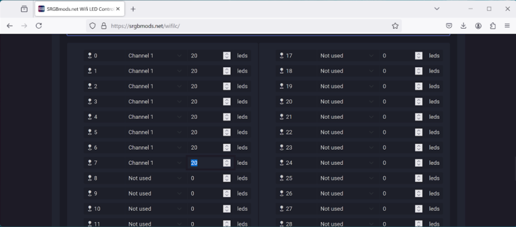
On this page, you can select which GPIO pins are used for outputs and how many LEDs are on each pin. The GPIO pins have to be sequential. We went for GPIOs 0–7. There’s not a fixed limit on the number of LEDs on each pin, though you will run out of RAM at some point. The more LEDs, the slower the updates are, so we’d recommend limiting it to about 100 or so per pin.
While there isn’t specific support for LED matrices, in most cases, you should be able to get them to work – see the box overleaf for details.
Once you’ve selected your configuration, click download and you’ll get a zip file that bundles the code together.
Compiling Code
The code is for the Arduino IDE, so you’ll need to download this from arduino.cc/en/software.
There are a few bits you need to configure in this – take a look at the red box on the firmware page (where you just set your configuration). It’s a bit different between the two versions of the firmware, but make sure you follow them, otherwise you’ll have problems. Once all this is done, plug your microcontroller into your computer via USB and click the arrow button to compile and upload.
The SRGBmods firmware works with WS2812B LEDs (aka NeoPixels). These typically come in strips, but you can get them in different form factors. Your LEDs should have three connections – one for power, one for ground, and one for data. The simplest possible configuration is to connect ground to ground on the microcontroller, power to VBUS, and signal to the appropriate GPIO pin.
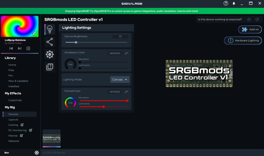
Now it’s time to set up the software on the PC side. You’ll need the SignalRGB software, which you can install from signalrgb.com. This is primarily designed for controlling the LEDs in fancy computer peripherals – the sort of setup where you have the keyboard backlights moving in time with the lights on the CPU cooler. We’re not going to do any of that, but we can use the same system to control our LEDs.
Once you’ve downloaded and installed it, you should be able to run it like any other application.
The next bit depends slightly on whether you’ve used the USB firmware or the Wi-Fi firmware. If you’ve used the USB firmware, then go to the devices option in the menu, and you should see an entry for SRGBmods LED Controller v1 (as well as possibly any other RGB hardware you have on your machine). If you don’t, you might find that you need to set it to run the software as administrator (follow this guide).
If you used the Wi-Fi firmware, then go into the Network menu, select SRGBmods from the list and follow the wizard to attach the device. You will need to know the IP address of the device – you should be able to find that out via your router’s admin interface.
The primary unit of SRGB isn’t devices, but strips. As far as SRGB is concerned, strips aren’t physical strips of LEDs joined together, but logical strips that you create in the application.
In the device section, go to the component config tab (which confusingly has an icon of connected circles usually used for social sharing). Here, you can click the ‘+’ to add a new strip. Change the LED count to whatever you want, then press Create to create the strip. This will use the first chunk of LEDs connected to your Pico, starting with the physical strip connected to the first GPIO and then overflowing, if necessary, onto the next physical strip. This isn’t based on the number of LEDs you have actually connected, but the number that you entered into the config box when you created the firmware. If you want, you can then create additional strips until all the LEDs are accounted for.

SRGB animations are two-dimensional, and you can place your various strips within this 2D space. This means that if you have multiple strips, you can place them so that they display suitable parts of this 2D pattern. This is all set up in the Layout section.
Here, you should see an entry for the device, which can drop down to show the various strips it contains. Click on these to add them to the layout, and you can move them around to capture the bits you want. In the bottom right, there’s a pane where you can control the position, scale, and rotation precisely, which is useful if you want to position multiple strips relative to each other.
Animation
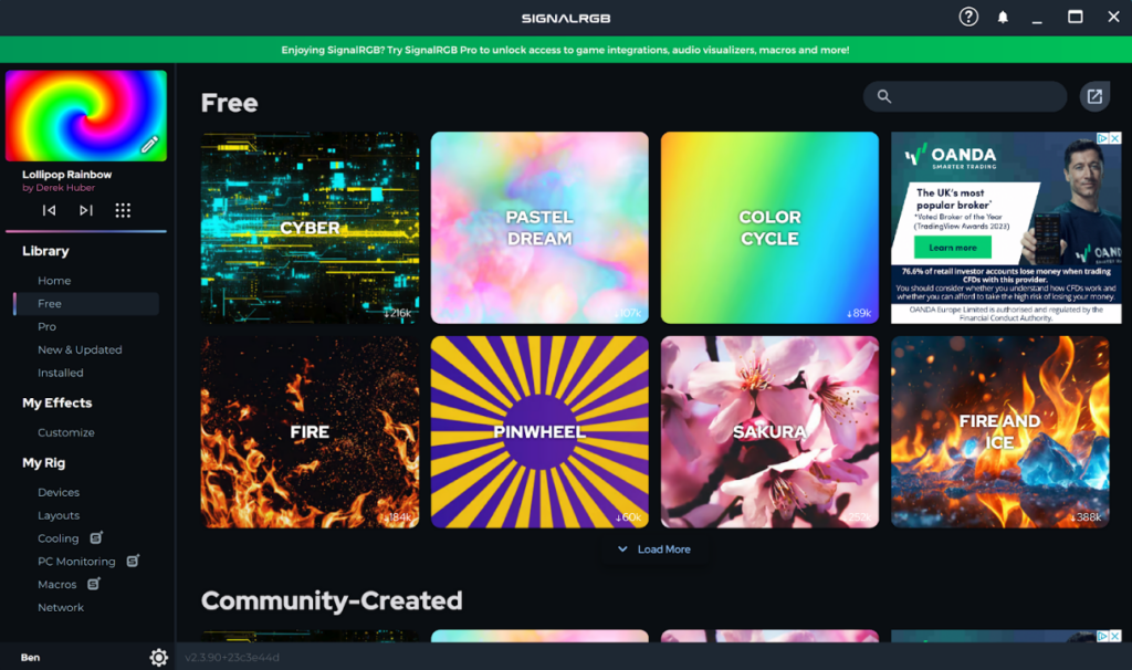
We’ve now done all the setup work, but we haven’t yet got an animation. There are ‘pro’ and ‘free’ animations. We’ve been playing with the free options, but no-doubt there are some interesting choices available in the paid-for tier as well.
Go to Library > Free in the left-hand side, and you should see the options. Click on an option to download it and you should then see it playing at the top of the left-hand pane. It should also start displaying on the LEDs at this point.
Any that you’ve downloaded also appear in the Installed section.
You should now have your LEDs flashing away according to the pattern you’ve picked. Have a hunt around the different options to find a setup you enjoy. You get the best effect when you use multiple strips to build up part of the 2D pattern. Remember the golden rule: if in doubt, add more LEDs.
The post Zero-code LED animations with Raspberry Pi Pico appeared first on Raspberry Pi.
from News - Raspberry Pi https://ift.tt/4WYkBMm
Labels: IFTTT, News - Raspberry Pi

0 Comments:
Post a Comment
Subscribe to Post Comments [Atom]
<< Home